

154
Practical MATLAB
® Applications for Engineers
Example 2.13
Using two loop equations and one node equation, and the matrix operations I =
inv(R) * V (where R is the [equivalent] impedance matrix of the network and V the
voltage vector), solve for the three branch currents—I 1 , I 2 , and I 3 —shown in the circuit
diagram of Figure 2.52.
ANALYTICAL Solution
The node and the two loop equations are shown as follows:
Node A;
−I 1 + I 2 + I 3 = 0
Loop# 1;
10 * I 1 + 5 * I 2 = 10
Loop# 2;
−5 * I 2 + (10 + 20) * I 3 = 0
The preceding equations in matrix form is given by
Ϫ
Ϫ
1 1 1
10 5 0
0
5 30
0
10
0
1
2
3
*
I
I
I
ϭ
Then the 3 × 3 matrix becomes the resistance matrix R, and the voltage V is given by the
column vector [0 10 0]
T as illustrated by the following matrix equation:
[ ] * [ ] [ ]
R I
V
ϭ
then
I = inv (R) * V
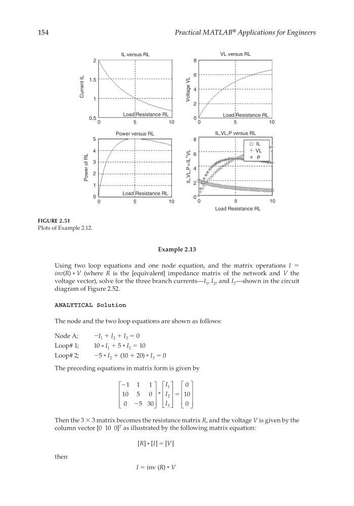
FIGURE 2.51
Plots of Example 2.12.
2
1.5
1
Current IL
Power of RL
0.5
0
5
IL versus RL
VL versus RL
8
6
4
Voltage VL
2
0
8
6
IL,VL,P = IL ∗
VL
IL,VL,P versus RL
IL
4
2
0
Power versus RL
Load Resistance RL
Load Resistance RL
Load Resistance RL
Load Resistance RL
10
0
5
10
0
5
1 0
0
0
1
2
3
4
5
5
1 0
P
VL
CRC_47760_CH002.indd 154
CRC_47760_CH002.indd 154
7/23/2008 1:38:49 PM
7/23/2008 1:38:49 PM
Practical MATLAB
® Applications for Engineers
Example 2.13
Using two loop equations and one node equation, and the matrix operations I =
inv(R) * V (where R is the [equivalent] impedance matrix of the network and V the
voltage vector), solve for the three branch currents—I 1 , I 2 , and I 3 —shown in the circuit
diagram of Figure 2.52.
ANALYTICAL Solution
The node and the two loop equations are shown as follows:
Node A;
−I 1 + I 2 + I 3 = 0
Loop# 1;
10 * I 1 + 5 * I 2 = 10
Loop# 2;
−5 * I 2 + (10 + 20) * I 3 = 0
The preceding equations in matrix form is given by
Ϫ
Ϫ
1 1 1
10 5 0
0
5 30
0
10
0
1
2
3
*
I
I
I
ϭ
Then the 3 × 3 matrix becomes the resistance matrix R, and the voltage V is given by the
column vector [0 10 0]
T as illustrated by the following matrix equation:
[ ] * [ ] [ ]
R I
V
ϭ
then
I = inv (R) * V
FIGURE 2.51
Plots of Example 2.12.
2
1.5
1
Current IL
Power of RL
0.5
0
5
IL versus RL
VL versus RL
8
6
4
Voltage VL
2
0
8
6
IL,VL,P = IL ∗
VL
IL,VL,P versus RL
IL
4
2
0
Power versus RL
Load Resistance RL
Load Resistance RL
Load Resistance RL
Load Resistance RL
10
0
5
10
0
5
1 0
0
0
1
2
3
4
5
5
1 0
P
VL
CRC_47760_CH002.indd 154
CRC_47760_CH002.indd 154
7/23/2008 1:38:49 PM
7/23/2008 1:38:49 PM