

772
A. Fraser and J.-M. Deschênes
These measurements indicate that the marking system can accommodate part
positioning variation of 13.6 mm for lead and 10.3 mm for zinc while keeping a
contrast value above 50%. If the positioning precision of the surface to mark is
within that range, a 2D laser head is an appropriate option. On the other hand, if the
part positioning process does not allow to be within that range, the solution must
include a 3D laser heads with dynamic part positioning compensation with integrated
distance sensors. Next section presents how to implement this.
Integration
Marking needs of lead and zinc smelters are typically either for large ingots (jumbos),
individual small ingots or small ingot bundles. All these needs are addressed by the
laser marking solution presented in this paper.
As shown in Fig. 7 of the previous section, in order to create a high contrast mark,
the focal spot needs to be within a few millimeters of the surface to mark (10.3 mm
for zinc, 13.6 mm for lead). Often this is not the case and we then must use a 3D
head combined with a laser distance sensor. The 3D head includes a moving lens
that allows to move the focus distance to keep it precisely on the surface. With this
feature, the allowable distance variation is much higher and reaches approximately
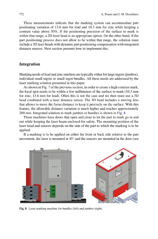
200 mm. Integrated solution to mark jumbos or bundles is shown in Fig. 8.
These machines have doors that open and close to let the part to mark go in and
out while keeping the laser beam enclosed for safety. The mounting position of the
laser head and sensors depends on the side of the part to which the marking is to be
applied.
If a marking is to be applied on either the front or back side relative to the part
movement, the laser is mounted at 45° and the sensors are mounted in the door (see
Fig. 8 Laser marking machine for bundles (left) and jumbos (right)