

True Traceability Enabled by In-Line …
771
0
10
20
30
40
50
60
70
80
90
0
2
4
6
8
10
12
14
Cell contrast (%)
Time (sec)
Pb
Zn
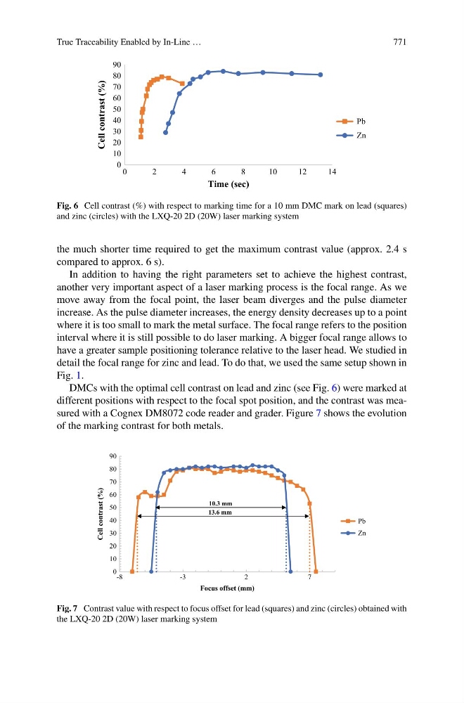
Fig. 6 Cell contrast (%) with respect to marking time for a 10 mm DMC mark on lead (squares)
and zinc (circles) with the LXQ-20 2D (20W) laser marking system
the much shorter time required to get the maximum contrast value (approx. 2.4 s
compared to approx. 6 s).
In addition to having the right parameters set to achieve the highest contrast,
another very important aspect of a laser marking process is the focal range. As we
move away from the focal point, the laser beam diverges and the pulse diameter
increase. As the pulse diameter increases, the energy density decreases up to a point
where it is too small to mark the metal surface. The focal range refers to the position
interval where it is still possible to do laser marking. A bigger focal range allows to
have a greater sample positioning tolerance relative to the laser head. We studied in
detail the focal range for zinc and lead. To do that, we used the same setup shown in
Fig. 1.
DMCs with the optimal cell contrast on lead and zinc (see Fig. 6) were marked at
different positions with respect to the focal spot position, and the contrast was measured with a Cognex DM8072 code reader and grader. Figure 7 shows the evolution
of the marking contrast for both metals.
0
10
20
30
40
50
60
70
80
90
-8
-3
2
7
Cell contrast (%)
Focus offset (mm)
Pb
Zn
10.3 mm
13.6 mm
Fig. 7 Contrast value with respect to focus offset for lead (squares) and zinc (circles) obtained with
the LXQ-20 2D (20W) laser marking system