

True Traceability Enabled by In-Line …
773
Bundle
Bundle
Camera
Distance sensors
Exit door
3D laser
marking head
Bundle Movement direction
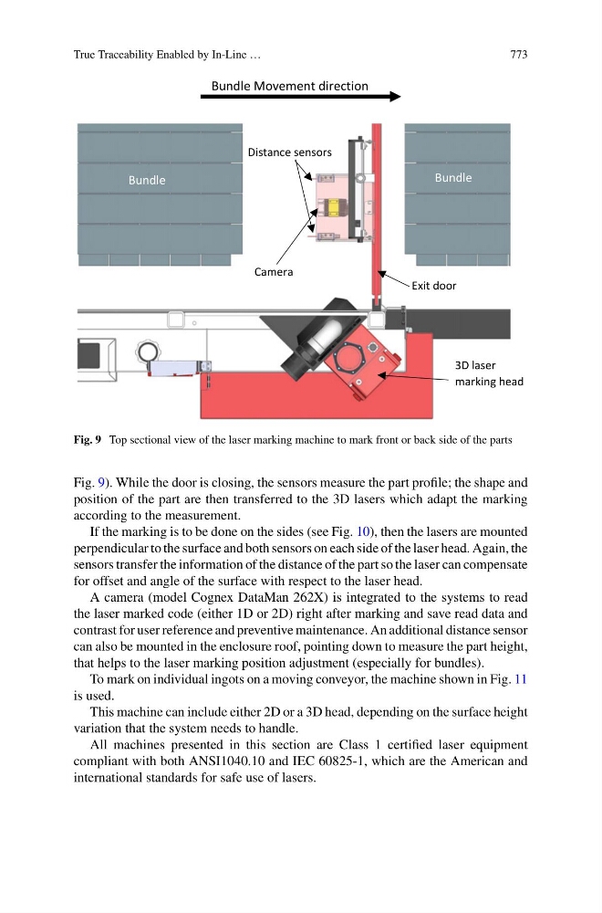
Fig. 9 Top sectional view of the laser marking machine to mark front or back side of the parts
Fig. 9). While the door is closing, the sensors measure the part profile; the shape and
position of the part are then transferred to the 3D lasers which adapt the marking
according to the measurement.
If the marking is to be done on the sides (see Fig. 10), then the lasers are mounted
perpendicular to the surface and both sensors on each side of the laser head. Again, the
sensors transfer the information of the distance of the part so the laser can compensate
for offset and angle of the surface with respect to the laser head.
A camera (model Cognex DataMan 262X) is integrated to the systems to read
the laser marked code (either 1D or 2D) right after marking and save read data and
contrast for user reference and preventive maintenance. An additional distance sensor
can also be mounted in the enclosure roof, pointing down to measure the part height,
that helps to the laser marking position adjustment (especially for bundles).
To mark on individual ingots on a moving conveyor, the machine shown in Fig. 11
is used.
This machine can include either 2D or a 3D head, depending on the surface height
variation that the system needs to handle.
All machines presented in this section are Class 1 certified laser equipment
compliant with both ANSI1040.10 and IEC 60825-1, which are the American and
international standards for safe use of lasers.