

77
Evaluation of Network-on-Chip Architectures
Tile
Router
2.5 mm
2.5 mm
≈20 mm
≈10
mm
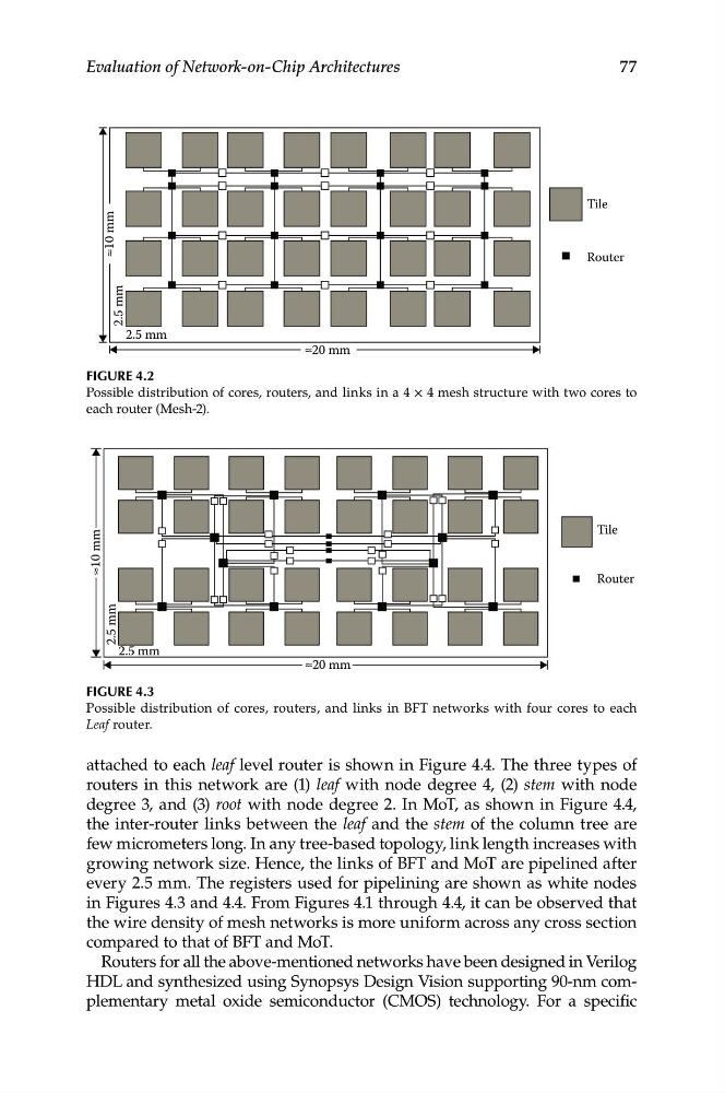
Figure 4.2
Possible distribution of cores, routers, and links in a 4 × 4 mesh structure with two cores to
each router (Mesh-2).
Tile
Router
≈20 mm
≈10
mm
2.5 mm
2.5 mm
Figure 4.3
Possible distribution of cores, routers, and links in BFT networks with four cores to each
Leaf router.
attached to each leaf level router is shown in Figure 4.4. The three types of
routers in this network are (1) leaf with node degree 4, (2) stem with node
degree 3, and (3) root with node degree 2. In MoT, as shown in Figure 4.4,
the inter-router links between the leaf and the stem of the column tree are
few micrometers long. In any tree-based topology, link length increases with
growing network size. Hence, the links of BFT and MoT are pipelined after
every 2.5 mm. The registers used for pipelining are shown as white nodes
in Figures 4.3 and 4.4. From Figures 4.1 through 4.4, it can be observed that
the wire density of mesh networks is more uniform across any cross section
compared to that of BFT and MoT.
Routers for all the above-mentioned networks have been designed in Verilog
HDL and synthesized using Synopsys Design Vision supporting 90-nm complementary metal oxide semiconductor (CMOS) technology. For a specific
Evaluation of Network-on-Chip Architectures
Tile
Router
2.5 mm
2.5 mm
≈20 mm
≈10
mm
Figure 4.2
Possible distribution of cores, routers, and links in a 4 × 4 mesh structure with two cores to
each router (Mesh-2).
Tile
Router
≈20 mm
≈10
mm
2.5 mm
2.5 mm
Figure 4.3
Possible distribution of cores, routers, and links in BFT networks with four cores to each
Leaf router.
attached to each leaf level router is shown in Figure 4.4. The three types of
routers in this network are (1) leaf with node degree 4, (2) stem with node
degree 3, and (3) root with node degree 2. In MoT, as shown in Figure 4.4,
the inter-router links between the leaf and the stem of the column tree are
few micrometers long. In any tree-based topology, link length increases with
growing network size. Hence, the links of BFT and MoT are pipelined after
every 2.5 mm. The registers used for pipelining are shown as white nodes
in Figures 4.3 and 4.4. From Figures 4.1 through 4.4, it can be observed that
the wire density of mesh networks is more uniform across any cross section
compared to that of BFT and MoT.
Routers for all the above-mentioned networks have been designed in Verilog
HDL and synthesized using Synopsys Design Vision supporting 90-nm complementary metal oxide semiconductor (CMOS) technology. For a specific