

69
Architecture Design of Network-on-Chip
status register. If more than one request signal is high at a time, the output
bits of the status register will be set on a cycle-by-cycle basis in the following order: b_1, b_2, b_3, … b_v. When all the status register bits are set, the
all_vc_busy signal will be at logic-1, which signifies that all the VCs of the next
router’s input link module are engaged. This all_vc_busy signal is used to
disable the tree arbiter as shown in Figure 3.14.
3.6.2.2 Switch Allocator
Individual flits are arbitrated to access the outgoing physical channels via
crossbar on each cycle by the switch allocator module. Switch allocator module needs two stages of arbitration (Mullins et al. 2004). The first stage has V:1
arbiter for each input VC.
It is followed by a second stage of P:1 arbiters for each output port. In
the modified router architecture, as all the request signals from each input
channel are coming to the crossbar, the first-stage arbiters are eliminated.
As the status register stores the status of each VC of the next router’s input
link module (Figure 3.15), the switch allocator module needs a V:1 arbiter to
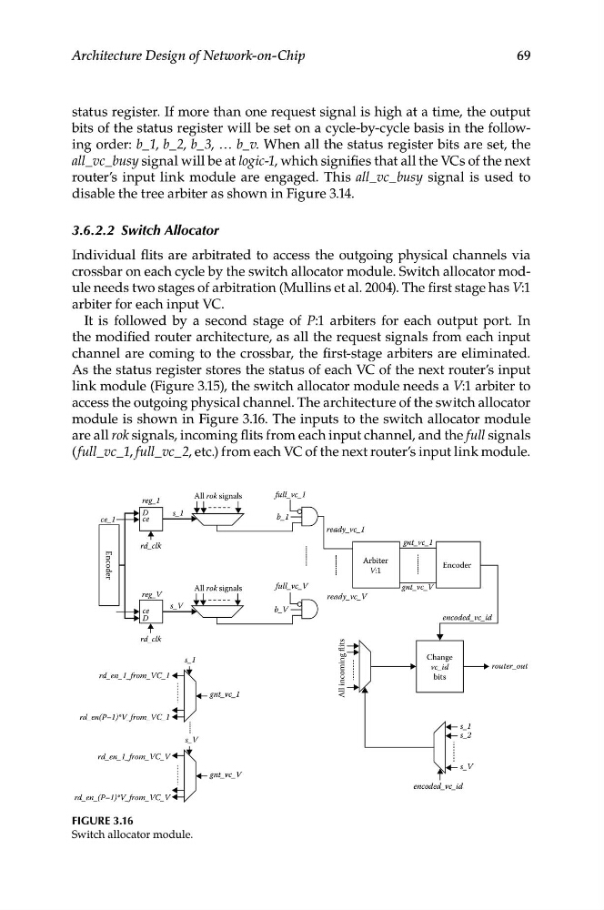
access the outgoing physical channel. The architecture of the switch allocator
module is shown in Figure 3.16. The inputs to the switch allocator module
are all rok signals, incoming flits from each input channel, and the full signals
(full_vc_1, full_vc_2, etc.) from each VC of the next router’s input link module.
All rok signals
full_vc_1
reg_1
ce_1
rd_clk
Encoder
D
ce
D
ce
reg_V
rd_clk
rd_en_1_from_VC_1
rd_en(P–1)*V_from_VC_1
rd_en_1_from_VC_V
rd_en_(P–1)*V_from_VC_V
ready_vc_1
gnt_vc_1
gnt_vc_V
All rok signals
full_vc_V
Arbiter
V:1
Encoder
encoded_vc_id
encoded_vc_id
Change
vc_id
bits
ready_vc_V
b_V
All incoming flits
s_1
b_1
s_V
s_1
s_V
gnt_vc_1
gnt_vc_V
s_1
s_2
s_V
router_out
Figure 3.16
Switch allocator module.
Architecture Design of Network-on-Chip
status register. If more than one request signal is high at a time, the output
bits of the status register will be set on a cycle-by-cycle basis in the following order: b_1, b_2, b_3, … b_v. When all the status register bits are set, the
all_vc_busy signal will be at logic-1, which signifies that all the VCs of the next
router’s input link module are engaged. This all_vc_busy signal is used to
disable the tree arbiter as shown in Figure 3.14.
3.6.2.2 Switch Allocator
Individual flits are arbitrated to access the outgoing physical channels via
crossbar on each cycle by the switch allocator module. Switch allocator module needs two stages of arbitration (Mullins et al. 2004). The first stage has V:1
arbiter for each input VC.
It is followed by a second stage of P:1 arbiters for each output port. In
the modified router architecture, as all the request signals from each input
channel are coming to the crossbar, the first-stage arbiters are eliminated.
As the status register stores the status of each VC of the next router’s input
link module (Figure 3.15), the switch allocator module needs a V:1 arbiter to
access the outgoing physical channel. The architecture of the switch allocator
module is shown in Figure 3.16. The inputs to the switch allocator module
are all rok signals, incoming flits from each input channel, and the full signals
(full_vc_1, full_vc_2, etc.) from each VC of the next router’s input link module.
All rok signals
full_vc_1
reg_1
ce_1
rd_clk
Encoder
D
ce
D
ce
reg_V
rd_clk
rd_en_1_from_VC_1
rd_en(P–1)*V_from_VC_1
rd_en_1_from_VC_V
rd_en_(P–1)*V_from_VC_V
ready_vc_1
gnt_vc_1
gnt_vc_V
All rok signals
full_vc_V
Arbiter
V:1
Encoder
encoded_vc_id
encoded_vc_id
Change
vc_id
bits
ready_vc_V
b_V
All incoming flits
s_1
b_1
s_V
s_1
s_V
gnt_vc_1
gnt_vc_V
s_1
s_2
s_V
router_out
Figure 3.16
Switch allocator module.