

vc–id
Input channel-1
vc–id
Input channel-2
Input channel-3
Input channel-4
Input channel-1
VC allocation
Switch allocation
Input channel-2
Input channel-3
Input channel-4
65
Architecture Design of Network-on-Chip
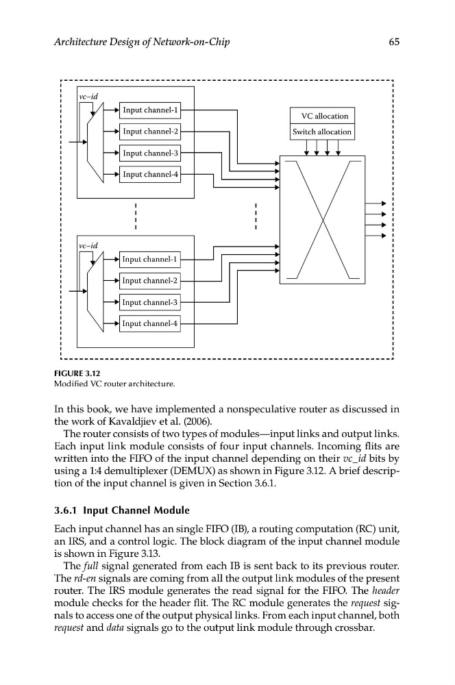
Figure 3.12
Modified VC router architecture.
In this book, we have implemented a nonspeculative router as discussed in
the work of Kavaldjiev et al. (2006).
The router consists of two types of modules—input links and output links.
Each input link module consists of four input channels. Incoming flits are
written into the FIFO of the input channel depending on their vc_id bits by
using a 1:4 demultiplexer (DEMUX) as shown in Figure 3.12. A brief description of the input channel is given in Section 3.6.1.
3.6.1 input Channel Module
Each input channel has an single FIFO (IB), a routing computation (RC) unit,
an IRS, and a control logic. The block diagram of the input channel module
is shown in Figure 3.13.
The full signal generated from each IB is sent back to its previous router.
The rd-en signals are coming from all the output link modules of the present
router. The IRS module generates the read signal for the FIFO. The header
module checks for the header flit. The RC module generates the request signals to access one of the output physical links. From each input channel, both
request and data signals go to the output link module through crossbar.
Input channel-1
vc–id
Input channel-2
Input channel-3
Input channel-4
Input channel-1
VC allocation
Switch allocation
Input channel-2
Input channel-3
Input channel-4
65
Architecture Design of Network-on-Chip
Figure 3.12
Modified VC router architecture.
In this book, we have implemented a nonspeculative router as discussed in
the work of Kavaldjiev et al. (2006).
The router consists of two types of modules—input links and output links.
Each input link module consists of four input channels. Incoming flits are
written into the FIFO of the input channel depending on their vc_id bits by
using a 1:4 demultiplexer (DEMUX) as shown in Figure 3.12. A brief description of the input channel is given in Section 3.6.1.
3.6.1 input Channel Module
Each input channel has an single FIFO (IB), a routing computation (RC) unit,
an IRS, and a control logic. The block diagram of the input channel module
is shown in Figure 3.13.
The full signal generated from each IB is sent back to its previous router.
The rd-en signals are coming from all the output link modules of the present
router. The IRS module generates the read signal for the FIFO. The header
module checks for the header flit. The RC module generates the request signals to access one of the output physical links. From each input channel, both
request and data signals go to the output link module through crossbar.