

64
Network-on-Chip
Output channel
Output channel
credits in
VC identifier
Routing logic
VC allocator
Switch allocator
Crossbar
(P × P)
VC identifier
Input channel
Input channel
credit out
v
VC buffer
Input port
v
VC buffer
credit out
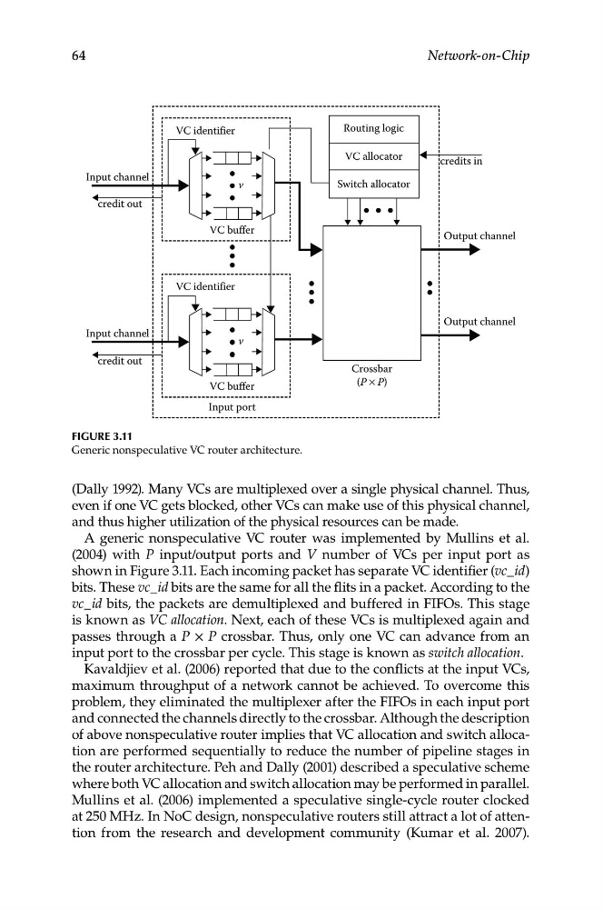
Figure 3.11
Generic nonspeculative VC router architecture.
(Dally 1992). Many VCs are multiplexed over a single physical channel. Thus,
even if one VC gets blocked, other VCs can make use of this physical channel,
and thus higher utilization of the physical resources can be made.
A generic nonspeculative VC router was implemented by Mullins et al.
(2004) with P input/output ports and V number of VCs per input port as
shown in Figure 3.11. Each incoming packet has separate VC identifier (vc_id)
bits. These vc_id bits are the same for all the flits in a packet. According to the
vc_id bits, the packets are demultiplexed and buffered in FIFOs. This stage
is known as VC allocation. Next, each of these VCs is multiplexed again and
passes through a P × P crossbar. Thus, only one VC can advance from an
input port to the crossbar per cycle. This stage is known as switch allocation.
Kavaldjiev et al. (2006) reported that due to the conflicts at the input VCs,
maximum throughput of a network cannot be achieved. To overcome this
problem, they eliminated the multiplexer after the FIFOs in each input port
and connected the channels directly to the crossbar. Although the description
of above nonspeculative router implies that VC allocation and switch allocation are performed sequentially to reduce the number of pipeline stages in
the router architecture. Peh and Dally (2001) described a speculative scheme
where both VC allocation and switch allocation may be performed in parallel.
Mullins et al. (2006) implemented a speculative single-cycle router clocked
at 250 MHz. In NoC design, nonspeculative routers still attract a lot of attention from the research and development community (Kumar et al. 2007).