

Link
control
Physical
channel
IB
IB
Physical
channel
Critical path
Header
flit
RC
RC
SA
Routing
algorithm
request
request
Header
flit
Crossbar
control
OB
OB
Link
control
Link
control
Physical
channel
Physical
channel
Link
control
Routing
algorithm
Crossbar (ST)
IB
RC
SA
ST
OB
(input buffering)
(route computation)
(switch allocator) (switch traversal)
(output buffering)
63
Architecture Design of Network-on-Chip
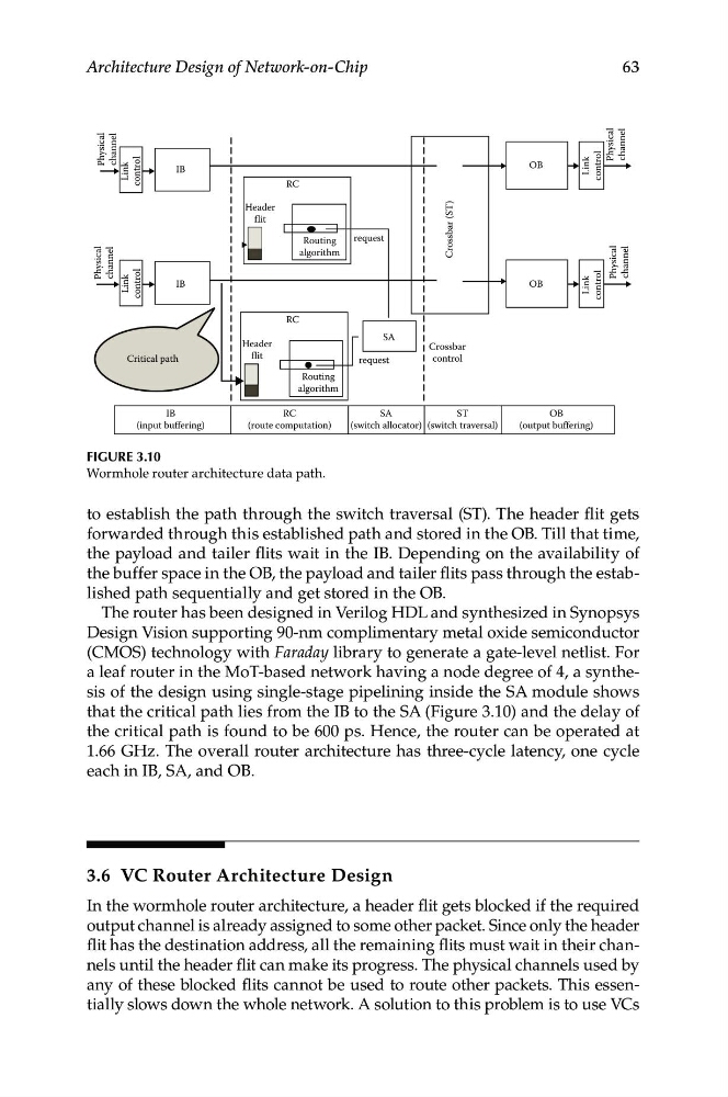
Figure 3.10
Wormhole router architecture data path.
to establish the path through the switch traversal (ST). The header flit gets
forwarded through this established path and stored in the OB. Till that time,
the payload and tailer flits wait in the IB. Depending on the availability of
the buffer space in the OB, the payload and tailer flits pass through the established path sequentially and get stored in the OB.
The router has been designed in Verilog HDL and synthesized in Synopsys
Design Vision supporting 90-nm complimentary metal oxide semiconductor
(CMOS) technology with Faraday library to generate a gate-level netlist. For
a leaf router in the MoT-based network having a node degree of 4, a synthesis of the design using single-stage pipelining inside the SA module shows
that the critical path lies from the IB to the SA (Figure 3.10) and the delay of
the critical path is found to be 600 ps. Hence, the router can be operated at
1.66 GHz. The overall router architecture has three-cycle latency, one cycle
each in IB, SA, and OB.
3.6 VC Router Architecture Design
In the wormhole router architecture, a header flit gets blocked if the required
output channel is already assigned to some other packet. Since only the header
flit has the destination address, all the remaining flits must wait in their channels until the header flit can make its progress. The physical channels used by
any of these blocked flits cannot be used to route other packets. This essentially slows down the whole network. A solution to this problem is to use VCs
control
Physical
channel
IB
IB
Physical
channel
Critical path
Header
flit
RC
RC
SA
Routing
algorithm
request
request
Header
flit
Crossbar
control
OB
OB
Link
control
Link
control
Physical
channel
Physical
channel
Link
control
Routing
algorithm
Crossbar (ST)
IB
RC
SA
ST
OB
(input buffering)
(route computation)
(switch allocator) (switch traversal)
(output buffering)
63
Architecture Design of Network-on-Chip
Figure 3.10
Wormhole router architecture data path.
to establish the path through the switch traversal (ST). The header flit gets
forwarded through this established path and stored in the OB. Till that time,
the payload and tailer flits wait in the IB. Depending on the availability of
the buffer space in the OB, the payload and tailer flits pass through the established path sequentially and get stored in the OB.
The router has been designed in Verilog HDL and synthesized in Synopsys
Design Vision supporting 90-nm complimentary metal oxide semiconductor
(CMOS) technology with Faraday library to generate a gate-level netlist. For
a leaf router in the MoT-based network having a node degree of 4, a synthesis of the design using single-stage pipelining inside the SA module shows
that the critical path lies from the IB to the SA (Figure 3.10) and the delay of
the critical path is found to be 600 ps. Hence, the router can be operated at
1.66 GHz. The overall router architecture has three-cycle latency, one cycle
each in IB, SA, and OB.
3.6 VC Router Architecture Design
In the wormhole router architecture, a header flit gets blocked if the required
output channel is already assigned to some other packet. Since only the header
flit has the destination address, all the remaining flits must wait in their channels until the header flit can make its progress. The physical channels used by
any of these blocked flits cannot be used to route other packets. This essentially slows down the whole network. A solution to this problem is to use VCs