

R
R
R
R
R
R
R
R
L
L
S
L
L
S
L
L
S
L
L
S
L
L
S
L
L
S
L
L
S
L
L
S
S
S
S
S
S
S
S
S
(a)
(b)
23
Interconnection Networks in Network-on-Chip
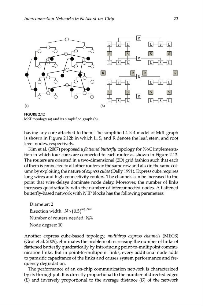
Figure 2.12
MoT topology (a) and its simplified graph (b).
having any core attached to them. The simplified 4 × 4 model of MoT graph
is shown in Figure 2.12b in which L, S, and R denote the leaf, stem, and root
level nodes, respectively.
Kim et al. (2007) proposed a flattened butterfly topology for NoC implementation in which four cores are connected to each router as shown in Figure 2.13.
The routers are oriented in a two-dimensional (2D) grid fashion such that each
of them is connected to all other routers in the same row and also in the same column by exploiting the nature of express cubes (Dally 1991). Express cube requires
long wires and high connectivity routers. The channels can be increased to the
point that wire delays dominate node delay. Moreover, the number of links
increases quadratically with the number of interconnected nodes. A flattened
butterfly-based network with N IP blocks has the following parameters:
Diameter: 2
log 2N/2
Bisection width: N × (0 5
. )
Number of routers needed: N/4
Node degree: 10
Another express cube-based topology, multidrop express channels (MECS)
(Grot et al. 2009), eliminates the problem of increasing the number of links of
flattened butterfly quadratically by introducing point-to-multipoint communication links. But in point-to-multipoint links, every additional node adds
to parasitic capacitance of the links and causes system performance and frequency degradation.
The performance of an on-chip communication network is characterized
by its throughput. It is directly proportional to the number of directed edges
(E) and inversely proportional to the average distance (D) of the network