

21
Interconnection Networks in Network-on-Chip
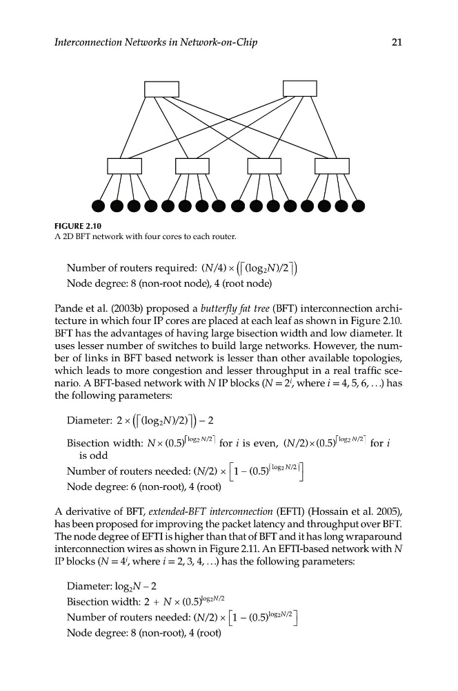
Figure 2.10
A 2D BFT network with four cores to each router.
Number of routers required: ( / ) × (⎡ ⎢ (log 2 N)/ 2⎤ ⎥ )
N 4
Node degree: 8 (non-root node), 4 (root node)
Pande et al. (2003b) proposed a butterfly fat tree (BFT) interconnection architecture in which four IP cores are placed at each leaf as shown in Figure 2.10.
BFT has the advantages of having large bisection width and low diameter. It
uses lesser number of switches to build large networks. However, the number of links in BFT based network is lesser than other available topologies,
which leads to more congestion and lesser throughput in a real traffic scenario. A BFT-based network with N IP blocks (N = 2 i , where i = 4, 5, 6, . . .) has
the following parameters:
Diameter: 2 × (⎡ ⎢ (log 2 N 2 ⎤ ⎥ ) −
)/ )
2
)
⎡ ⎢ log 2 N/2
)
⎡ ⎢ log 2 N/2
Bisection width: N × (0 5
⎤ ⎥
for i is even, (N/ ) ( 0 5
⎤ ⎥
for i
.
2 × .
is odd
)
⎡ ⎢ log 2 N/2⎤ ⎥ ⎤
Number of routers needed: ( / )
1 − (0 5
N 2 × ⎡
.
⎣
⎦
Node degree: 6 (non-root), 4 (root)
A derivative of BFT, extended-BFT interconnection (EFTI) (Hossain et al. 2005),
has been proposed for improving the packet latency and throughput over BFT.
The node degree of EFTI is higher than that of BFT and it has long wraparound
interconnection wires as shown in Figure 2.11. An EFTI-based network with N
IP blocks (N = 4 i , where i = 2, 3, 4, . . .) has the following parameters:
Diameter: log 2 N – 2
log 2N/2
Bisection width: 2 + N × (0 5
. )
log 2N/2
Number of routers needed: ( / )
N × ⎡
⎣
(0 5 )
⎤
⎦
2
1 − .
Node degree: 8 (non-root), 4 (root)