

342
Network-on-Chip
networks is the least among all the networks under uniformly distributed
traffic. For localized traffic, although its throughput increases with increasing
locality factor, it has the minimum value compared to other networks. This is
due to the fact that BFT-based networks are more congested as there are three
destination cores in the local cluster and lesser number of edges.
In Mesh-1 network, localized traffic is constrained within the destinations
placed at the shortest Manhattan distance, whereas Mesh-2 network enjoys
the advantage of having only a single core in its local clusters. In case of
highly localized traffic, the benefit of connecting two cores in each router
becomes clearly visible, as depicted in Table 11.5. The proposed MoT-based
NoC also has a single destination core in its local cluster. Thus, at highly
localized traffic, more packets will reach their destinations, resulting in
higher throughput.
Table 11.5 also compares the throughput of 3D networks with their 2D
counterparts. Intuitively, it can be stated that as the number of packets traversing toward the local cluster increases with increasing locality factor, the
difference of average hop count between 2D and 3D structures converges.
Hence, at highly localized traffic, increment in throughput of 3D networks is
lesser than that of 2D networks.
11.3.3.3 Average Overall Latency under Localized Traffic
In a contention-free environment, zero-load latency (in cycles) is another
widely used performance metric. Zero-load latency of a network is the
latency where only one packet traverses through the network (Pavlidis and
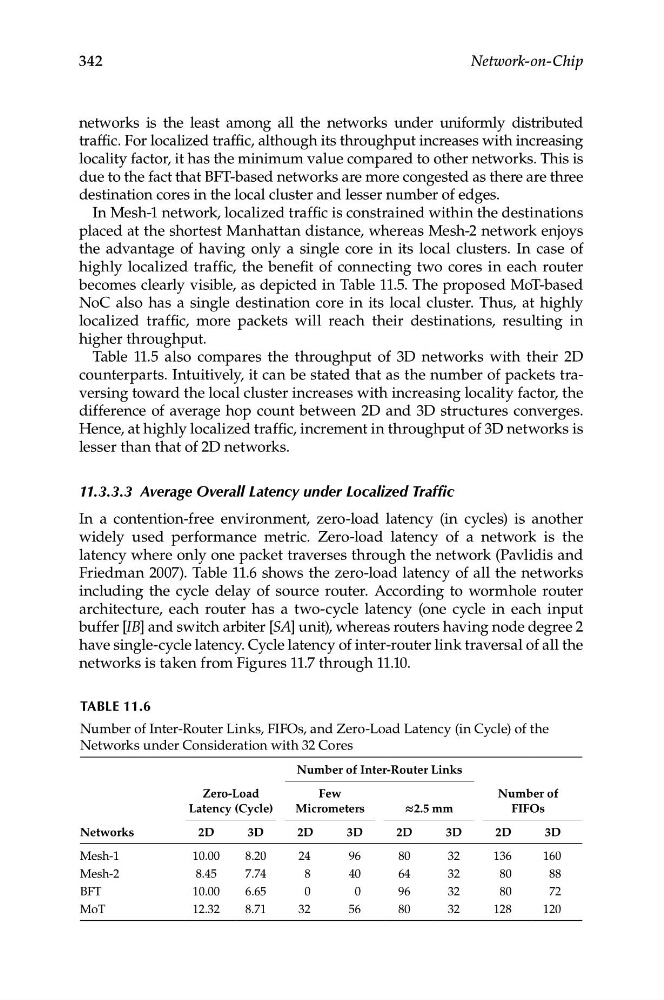
Friedman 2007). Table 11.6 shows the zero-load latency of all the networks
including the cycle delay of source router. According to wormhole router
architecture, each router has a two-cycle latency (one cycle in each input
buffer [IB] and switch arbiter [SA] unit), whereas routers having node degree 2
have single-cycle latency. Cycle latency of inter-router link traversal of all the
networks is taken from Figures 11.7 through 11.10.
TABLe 11.6
Number of Inter-Router Links, FIFOs, and Zero-Load Latency (in Cycle) of the
Networks under Consideration with 32 Cores
Zero-Load
Number of Inter-Router Links
Few
Number of
Latency (Cycle)
Micrometers
≈2.5 mm
FIFOs
2D
3D
136
160
Networks
Mesh-1
2D
3D
10.00
8.20
2D
3D
2D
3D
24
96
80
32
Mesh-2
8.45
7.74
8
40
64
32
80
88
BFT
10.00
6.65
0
0
96
32
80
72
MoT
12.32
8.71
32
56
80
32
128
120
Network-on-Chip
networks is the least among all the networks under uniformly distributed
traffic. For localized traffic, although its throughput increases with increasing
locality factor, it has the minimum value compared to other networks. This is
due to the fact that BFT-based networks are more congested as there are three
destination cores in the local cluster and lesser number of edges.
In Mesh-1 network, localized traffic is constrained within the destinations
placed at the shortest Manhattan distance, whereas Mesh-2 network enjoys
the advantage of having only a single core in its local clusters. In case of
highly localized traffic, the benefit of connecting two cores in each router
becomes clearly visible, as depicted in Table 11.5. The proposed MoT-based
NoC also has a single destination core in its local cluster. Thus, at highly
localized traffic, more packets will reach their destinations, resulting in
higher throughput.
Table 11.5 also compares the throughput of 3D networks with their 2D
counterparts. Intuitively, it can be stated that as the number of packets traversing toward the local cluster increases with increasing locality factor, the
difference of average hop count between 2D and 3D structures converges.
Hence, at highly localized traffic, increment in throughput of 3D networks is
lesser than that of 2D networks.
11.3.3.3 Average Overall Latency under Localized Traffic
In a contention-free environment, zero-load latency (in cycles) is another
widely used performance metric. Zero-load latency of a network is the
latency where only one packet traverses through the network (Pavlidis and
Friedman 2007). Table 11.6 shows the zero-load latency of all the networks
including the cycle delay of source router. According to wormhole router
architecture, each router has a two-cycle latency (one cycle in each input
buffer [IB] and switch arbiter [SA] unit), whereas routers having node degree 2
have single-cycle latency. Cycle latency of inter-router link traversal of all the
networks is taken from Figures 11.7 through 11.10.
TABLe 11.6
Number of Inter-Router Links, FIFOs, and Zero-Load Latency (in Cycle) of the
Networks under Consideration with 32 Cores
Zero-Load
Number of Inter-Router Links
Few
Number of
Latency (Cycle)
Micrometers
≈2.5 mm
FIFOs
2D
3D
136
160
Networks
Mesh-1
2D
3D
10.00
8.20
2D
3D
2D
3D
24
96
80
32
Mesh-2
8.45
7.74
8
40
64
32
80
88
BFT
10.00
6.65
0
0
96
32
80
72
MoT
12.32
8.71
32
56
80
32
128
120