

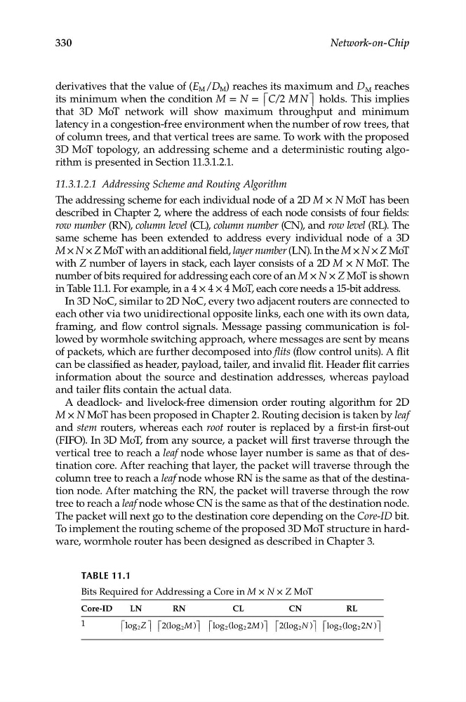
TABLe 11.1
Bits Required for Addressing a Core in M × N × Z MoT
Core-ID
LN
RN
CL
CN
RL
1
⎡ ⎢ log 2 Z ⎤ ⎥ ⎡
⎢ 2(log 2 M )⎤ ⎥ ⎡
⎢ log 2 (log 2 2M )⎤ ⎥ ⎡ ⎢ 2(log 2 N )⎤ ⎥ ⎡ ⎢ log 2 (log 2 2N )⎤ ⎥
330
Network-on-Chip
derivatives that the value of (E M /D M ) reaches its maximum and D M reaches
its minimum when the condition M = N = ⎡ ⎢ C/2 M N ⎤ ⎥ holds. This implies
that 3D MoT network will show maximum throughput and minimum
latency in a congestion-free environment when the number of row trees, that
of column trees, and that vertical trees are same. To work with the proposed
3D MoT topology, an addressing scheme and a deterministic routing algorithm is presented in Section 11.3.1.2.1.
11.3.1.2.1 Addressing Scheme and Routing Algorithm
The addressing scheme for each individual node of a 2D M × N MoT has been
described in Chapter 2, where the address of each node consists of four fields:
row number (RN), column level (CL), column number (CN), and row level (RL). The
same scheme has been extended to address every individual node of a 3D
M × N × Z MoT with an additional field, layer number (LN). In the M × N × Z MoT
with Z number of layers in stack, each layer consists of a 2D M × N MoT. The
number of bits required for addressing each core of an M × N × Z MoT is shown
in Table 11.1. For example, in a 4 × 4 × 4 MoT, each core needs a 15-bit address.
In 3D NoC, similar to 2D NoC, every two adjacent routers are connected to
each other via two unidirectional opposite links, each one with its own data,
framing, and flow control signals. Message passing communication is followed by wormhole switching approach, where messages are sent by means
of packets, which are further decomposed into flits (flow control units). A flit
can be classified as header, payload, tailer, and invalid flit. Header flit carries
information about the source and destination addresses, whereas payload
and tailer flits contain the actual data.
A deadlock- and livelock-free dimension order routing algorithm for 2D
M × N MoT has been proposed in Chapter 2. Routing decision is taken by leaf
and stem routers, whereas each root router is replaced by a first-in first-out
(FIFO). In 3D MoT, from any source, a packet will first traverse through the
vertical tree to reach a leaf node whose layer number is same as that of destination core. After reaching that layer, the packet will traverse through the
column tree to reach a leaf node whose RN is the same as that of the destination node. After matching the RN, the packet will traverse through the row
tree to reach a leaf node whose CN is the same as that of the destination node.
The packet will next go to the destination core depending on the Core-ID bit.
To implement the routing scheme of the proposed 3D MoT structure in hardware, wormhole router has been designed as described in Chapter 3.