

C1
C2
C3
C5
C6
C7
C9
C10
C11
C4
C8
C12
C13
C14
C15
C16
(a)
C1
C2
R
R
R
R
R
R
R
R
R
C3
C4
C5
C6
C7
C8
C9
C10
C11
C12
C13
C14
C15
C16
R
R
R
R
R
R
R
C1
C2
C3
C4
C5
C6
C7
C8
C9
C10
C11
C12
C13
C14
C15
C16
(b)
(c)
306
Network-on-Chip
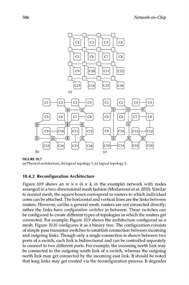
Figure 10.7
(a) Physical architecture; (b) logical topology 1; (c) logical topology 2.
10.4.2 reconfiguration Architecture
Figure 10.9 shows an m × n (4 × 4, in the example) network with nodes
arranged in a two-dimensional mesh fashion (Modarressi et al. 2010). Similar
to normal mesh, the square boxes correspond to routers to which individual
cores can be attached. The horizontal and vertical lines are the links between
routers. However, unlike a general mesh, routers are not connected directly;
rather the links have configuration switches in between. These switches can
be configured to create different types of topologies in which the routers get
connected. For example, Figure 10.9 shows the architecture configured as a
mesh. Figure 10.10 configures it as a binary tree. The configuration consists
of simple pass transistor switches to establish connection between incoming
and outgoing links. Though only a single connection is shown between two
ports of a switch, each link is bidirectional and can be controlled separately
to connect to two different ports. For example, the incoming north link may
be connected to the outgoing south link of a switch, whereas the outgoing
north link may get connected by the incoming east link. It should be noted
that long links may get created via the reconfiguration process. It degrades
C2
C3
C5
C6
C7
C9
C10
C11
C4
C8
C12
C13
C14
C15
C16
(a)
C1
C2
R
R
R
R
R
R
R
R
R
C3
C4
C5
C6
C7
C8
C9
C10
C11
C12
C13
C14
C15
C16
R
R
R
R
R
R
R
C1
C2
C3
C4
C5
C6
C7
C8
C9
C10
C11
C12
C13
C14
C15
C16
(b)
(c)
306
Network-on-Chip
Figure 10.7
(a) Physical architecture; (b) logical topology 1; (c) logical topology 2.
10.4.2 reconfiguration Architecture
Figure 10.9 shows an m × n (4 × 4, in the example) network with nodes
arranged in a two-dimensional mesh fashion (Modarressi et al. 2010). Similar
to normal mesh, the square boxes correspond to routers to which individual
cores can be attached. The horizontal and vertical lines are the links between
routers. However, unlike a general mesh, routers are not connected directly;
rather the links have configuration switches in between. These switches can
be configured to create different types of topologies in which the routers get
connected. For example, Figure 10.9 shows the architecture configured as a
mesh. Figure 10.10 configures it as a binary tree. The configuration consists
of simple pass transistor switches to establish connection between incoming
and outgoing links. Though only a single connection is shown between two
ports of a switch, each link is bidirectional and can be controlled separately
to connect to two different ports. For example, the incoming north link may
be connected to the outgoing south link of a switch, whereas the outgoing
north link may get connected by the incoming east link. It should be noted
that long links may get created via the reconfiguration process. It degrades