

i – 1
1
Lines
i
1
i + 1
1
State in Figure 8.1
s1
0
0
0
s2
1
1
1
s3
0
1
0
s4
1
0
1
s5
0
1
0
s6
0
0
0
s7
1
0
1
s8
238
Network-on-Chip
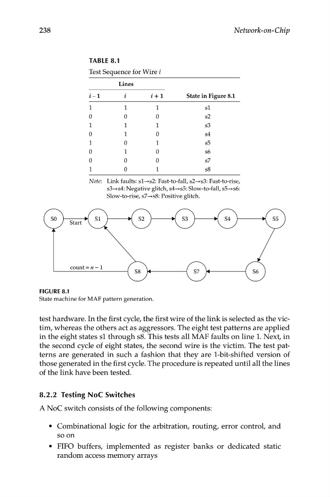
TABLe 8.1
Test Sequence for Wire i
Note: Link faults: s1→s2: Fast-to-fall, s2→s3: Fast-to-rise,
s3→s4: Negative glitch, s4→s5: Slow-to-fall, s5→s6:
Slow-to-rise, s7→s8: Positive glitch.
S0
S1
S8
S7
S6
S2
S3
S4
S5
Start
count = n − 1
Figure 8.1
State machine for MAF pattern generation.
test hardware. In the first cycle, the first wire of the link is selected as the victim, whereas the others act as aggressors. The eight test patterns are applied
in the eight states s1 through s8. This tests all MAF faults on line 1. Next, in
the second cycle of eight states, the second wire is the victim. The test patterns are generated in such a fashion that they are 1-bit-shifted version of
those generated in the first cycle. The procedure is repeated until all the lines
of the link have been tested.
8.2.2 Testing NoC Switches
A NoC switch consists of the following components:
• Combinational logic for the arbitration, routing, error control, and
so on
• FIFO buffers, implemented as register banks or dedicated static
random access memory arrays
1
Lines
i
1
i + 1
1
State in Figure 8.1
s1
0
0
0
s2
1
1
1
s3
0
1
0
s4
1
0
1
s5
0
1
0
s6
0
0
0
s7
1
0
1
s8
238
Network-on-Chip
TABLe 8.1
Test Sequence for Wire i
Note: Link faults: s1→s2: Fast-to-fall, s2→s3: Fast-to-rise,
s3→s4: Negative glitch, s4→s5: Slow-to-fall, s5→s6:
Slow-to-rise, s7→s8: Positive glitch.
S0
S1
S8
S7
S6
S2
S3
S4
S5
Start
count = n − 1
Figure 8.1
State machine for MAF pattern generation.
test hardware. In the first cycle, the first wire of the link is selected as the victim, whereas the others act as aggressors. The eight test patterns are applied
in the eight states s1 through s8. This tests all MAF faults on line 1. Next, in
the second cycle of eight states, the second wire is the victim. The test patterns are generated in such a fashion that they are 1-bit-shifted version of
those generated in the first cycle. The procedure is repeated until all the lines
of the link have been tested.
8.2.2 Testing NoC Switches
A NoC switch consists of the following components:
• Combinational logic for the arbitration, routing, error control, and
so on
• FIFO buffers, implemented as register banks or dedicated static
random access memory arrays