

239
Testing of Network-on-Chip Architectures
Test patterns can be generated for the combinational part using any automated
test pattern generation (ATPG) tool. Normally, scan-based testing strategies
are adopted for testing these blocks. For the FIFO part, a FIFO falls under the
category of restricted two-port memories. Since the data flow through the
NoC links is unidirectional in nature, each FIFO possesses one write-only
port and one read-only port. The functionality of the FIFO can then be considered to be divided into three ways: the memory cell array, the addressing
mechanism, and the FIFO-specific functions (such as empty/full conditions).
The memory array fault models can include stuck-at faults, transition faults,
bridging faults, and so on (Bushnell and Agrawal 2005).
Assuming that a FIFO is b-bit wide and has n locations, individual test patterns are of b bits each. For example, to detect a bridging fault between bits
b i and b j (i ≠ j), four specific test patterns are needed: 0101…, 1010…, 0000…,
and 1111 . . . . To test for dual-port coupling faults, the following sequence is
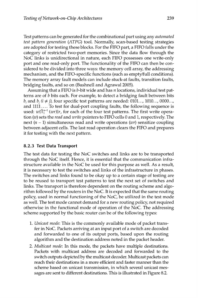
used: w{⇑ 1
n−1 (wr )} r, for each of the four test patterns. The first write operation (w) sets the read and write pointers to FIFO cells 0 and 1, respectively. The
next (n – 1) simultaneous read and write operations (wr) sensitize coupling
between adjacent cells. The last read operation clears the FIFO and prepares
it for testing with the next pattern.
8.2.3 Test Data Transport
The test data for testing the NoC switches and links are to be transported
through the NoC itself. Hence, it is essential that the communication infrastructure available in the NoC be used for this purpose as well. As a result,
it is necessary to test the switches and links of the infrastructure in phases.
The switches and links found to be okay up to a certain stage of testing are
to be reused to transport test patterns to test the next set of switches and
links. The transport is therefore dependent on the routing scheme and algorithm followed by the routers in the NoC. It is expected that the same routing
policy, used in normal functioning of the NoC, be utilized in the test mode
as well. The test mode cannot demand for a new routing policy, not required
otherwise in the functional mode of operation of the NoC. The addressing
scheme supported by the basic router can be of the following types:
1. Unicast mode: This is the commonly available mode of packet transfer in NoC. Packets arriving at an input port of a switch are decoded
and forwarded to one of its output ports, based upon the routing
algorithm and the destination address noted in the packet header.
2. Multicast mode: In this mode, the packets have multiple destinations.
Packets with multicast address are decoded and forwarded to the
switch outputs depicted by the multicast decoder. Multicast packets can
reach their destinations in a more efficient and faster manner than the
scheme based on unicast transmission, in which several unicast messages are sent to different destinations. This is illustrated in Figure 8.2.