

Encoder
Decoder
BIH
BI
Metric
computation
DAP
DAP
0 2:1
Mux
2:1
Mux
1
0
1
BIH
227
Signal Integrity and Reliability of Network-on-Chip
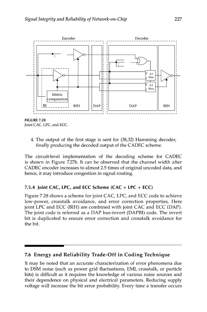
Figure 7.28
Joint CAC, LPC, and ECC.
4. The output of the first stage is sent for (38,32) Hamming decoder,
finally producing the decoded output of the CADEC scheme.
The circuit-level implementation of the decoding scheme for CADEC
is shown in Figure 7.27b. It can be observed that the channel width after
CADEC encoder increases to almost 2.5 times of original uncoded data, and
hence, it may introduce congestion in signal routing.
7.5.4 Joint CAC, LPC, and eCC Scheme (CAC + LPC + eCC)
Figure 7.28 shows a scheme for joint CAC, LPC, and ECC code to achieve
low-power, crosstalk avoidance, and error correction properties. Here
joint LPC and ECC (BIH) are combined with joint CAC and ECC (DAP).
The joint code is referred as a DAP bus-invert (DAPBI) code. The invert
bit is duplicated to ensure error correction and crosstalk avoidance for
the bit.
7.6 Energy and Reliability Trade-Off in Coding Technique
It may be noted that an accurate characterization of error phenomena due
to DSM noise (such as power grid fluctuations, EMI, crosstalk, or particle
hits) is difficult as it requires the knowledge of various noise sources and
their dependence on physical and electrical parameters. Reducing supply
voltage will increase the bit error probability. Every time a transfer occurs