

Triplication
Decoder
X 0
TMR
TMR
TMR
TMR
F M
F M = ab + bc + ca
Channels
a
b
c
X 1
X k−1
X 0
X 1
X k−1
Majority gate:
225
Signal Integrity and Reliability of Network-on-Chip
The BSC is very similar to DAP in that it uses duplication and one parity
bit to achieve crosstalk avoidance and SEC. However, the fundamental difference is that at each clock cycle, the parity bit is placed on the opposite side
of the encoded flit. Table 7.6 shows examples of different CAC + ECC code
words. The parity bits are indicated in bold. Pande et al. (2006b) observed
that the energy saving in DAP and MDR is almost the same for mesh and
folded torus topologies at 130-nm technology. The BSC scheme has less
energy saving compared to DAP and MDR.
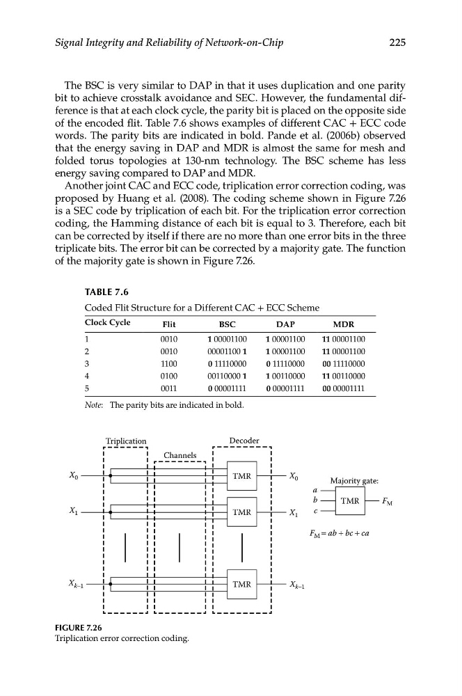
Another joint CAC and ECC code, triplication error correction coding, was
proposed by Huang et al. (2008). The coding scheme shown in Figure 7.26
is a SEC code by triplication of each bit. For the triplication error correction
coding, the Hamming distance of each bit is equal to 3. Therefore, each bit
can be corrected by itself if there are no more than one error bits in the three
triplicate bits. The error bit can be corrected by a majority gate. The function
of the majority gate is shown in Figure 7.26.
TABLe 7.6
Coded Flit Structure for a Different CAC + ECC Scheme
Clock Cycle
Flit
BSC
DAP
MDR
1
0010
1 00001100
1 00001100
11 00001100
2
0010
00001100 1
1 00001100
11 00001100
3
1100
0 11110000
0 11110000
00 11110000
4
0100
00110000 1
1 00110000
11 00110000
5
0011
0 00001111
0 00001111
00 00001111
Note: The parity bits are indicated in bold.
Figure 7.26
Triplication error correction coding.