

k
k
n
Router
Encoder
Decoder
Router
212
Network-on-Chip
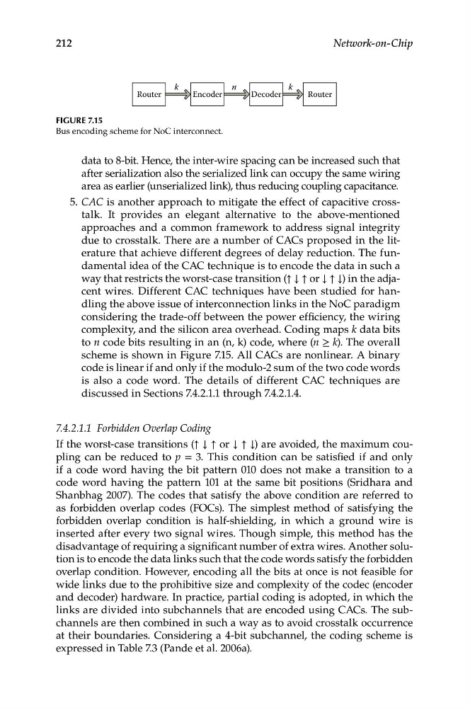
Figure 7.15
Bus encoding scheme for NoC interconnect.
data to 8-bit. Hence, the inter-wire spacing can be increased such that
after serialization also the serialized link can occupy the same wiring
area as earlier (unserialized link), thus reducing coupling capacitance.
5. CAC is another approach to mitigate the effect of capacitive crosstalk. It provides an elegant alternative to the above-mentioned
approaches and a common framework to address signal integrity
due to crosstalk. There are a number of CACs proposed in the literature that achieve different degrees of delay reduction. The fundamental idea of the CAC technique is to encode the data in such a
way that restricts the worst-case transition (↑ ↓ ↑ or ↓ ↑ ↓) in the adjacent wires. Different CAC techniques have been studied for handling the above issue of interconnection links in the NoC paradigm
considering the trade-off between the power efficiency, the wiring
complexity, and the silicon area overhead. Coding maps k data bits
to n code bits resulting in an (n, k) code, where (n ≥ k). The overall
scheme is shown in Figure 7.15. All CACs are nonlinear. A binary
code is linear if and only if the modulo-2 sum of the two code words
is also a code word. The details of different CAC techniques are
discussed in Sections 7.4.2.1.1 through 7.4.2.1.4.
7.4.2.1.1 Forbidden Overlap Coding
If the worst-case transitions (↑ ↓ ↑ or ↓ ↑ ↓) are avoided, the maximum coupling can be reduced to p = 3. This condition can be satisfied if and only
if a code word having the bit pattern 010 does not make a transition to a
code word having the pattern 101 at the same bit positions (Sridhara and
Shanbhag 2007). The codes that satisfy the above condition are referred to
as forbidden overlap codes (FOCs). The simplest method of satisfying the
forbidden overlap condition is half-shielding, in which a ground wire is
inserted after every two signal wires. Though simple, this method has the
disadvantage of requiring a significant number of extra wires. Another solution is to encode the data links such that the code words satisfy the forbidden
overlap condition. However, encoding all the bits at once is not feasible for
wide links due to the prohibitive size and complexity of the codec (encoder
and decoder) hardware. In practice, partial coding is adopted, in which the
links are divided into subchannels that are encoded using CACs. The subchannels are then combined in such a way as to avoid crosstalk occurrence
at their boundaries. Considering a 4-bit subchannel, the coding scheme is
expressed in Table 7.3 (Pande et al. 2006a).
k
n
Router
Encoder
Decoder
Router
212
Network-on-Chip
Figure 7.15
Bus encoding scheme for NoC interconnect.
data to 8-bit. Hence, the inter-wire spacing can be increased such that
after serialization also the serialized link can occupy the same wiring
area as earlier (unserialized link), thus reducing coupling capacitance.
5. CAC is another approach to mitigate the effect of capacitive crosstalk. It provides an elegant alternative to the above-mentioned
approaches and a common framework to address signal integrity
due to crosstalk. There are a number of CACs proposed in the literature that achieve different degrees of delay reduction. The fundamental idea of the CAC technique is to encode the data in such a
way that restricts the worst-case transition (↑ ↓ ↑ or ↓ ↑ ↓) in the adjacent wires. Different CAC techniques have been studied for handling the above issue of interconnection links in the NoC paradigm
considering the trade-off between the power efficiency, the wiring
complexity, and the silicon area overhead. Coding maps k data bits
to n code bits resulting in an (n, k) code, where (n ≥ k). The overall
scheme is shown in Figure 7.15. All CACs are nonlinear. A binary
code is linear if and only if the modulo-2 sum of the two code words
is also a code word. The details of different CAC techniques are
discussed in Sections 7.4.2.1.1 through 7.4.2.1.4.
7.4.2.1.1 Forbidden Overlap Coding
If the worst-case transitions (↑ ↓ ↑ or ↓ ↑ ↓) are avoided, the maximum coupling can be reduced to p = 3. This condition can be satisfied if and only
if a code word having the bit pattern 010 does not make a transition to a
code word having the pattern 101 at the same bit positions (Sridhara and
Shanbhag 2007). The codes that satisfy the above condition are referred to
as forbidden overlap codes (FOCs). The simplest method of satisfying the
forbidden overlap condition is half-shielding, in which a ground wire is
inserted after every two signal wires. Though simple, this method has the
disadvantage of requiring a significant number of extra wires. Another solution is to encode the data links such that the code words satisfy the forbidden
overlap condition. However, encoding all the bits at once is not feasible for
wide links due to the prohibitive size and complexity of the codec (encoder
and decoder) hardware. In practice, partial coding is adopted, in which the
links are divided into subchannels that are encoded using CACs. The subchannels are then combined in such a way as to avoid crosstalk occurrence
at their boundaries. Considering a 4-bit subchannel, the coding scheme is
expressed in Table 7.3 (Pande et al. 2006a).