

Signal Integrity and Reliability of Network-on-Chip
213
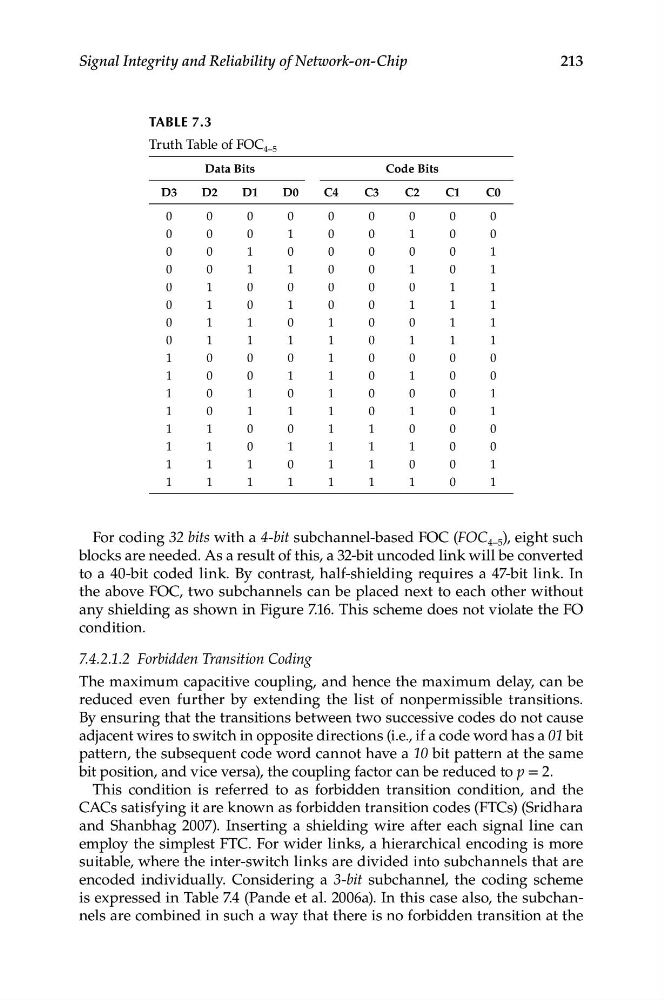
TABLe 7.3
Truth Table of FOC 4–5
Data Bits
D3
D2
D1
D0
0
0
0
0
0
0
0
1
0
0
1
0
0
0
1
1
0
1
0
0
0
1
0
1
0
1
1
0
0
1
1
1
1
0
0
0
1
0
0
1
1
0
1
0
1
0
1
1
1
1
0
0
1
1
0
1
1
1
1
0
1
1
1
1
C4
0
0
0
0
0
0
1
1
1
1
1
1
1
1
1
1
Code Bits
C3
C2
C1
0
0
0
0
1
0
0
0
0
0
1
0
0
0
1
0
1
1
0
0
1
0
1
1
0
0
0
0
1
0
0
0
0
0
1
0
1
0
0
1
1
0
1
0
0
1
1
0
C0
0
0
1
1
1
1
1
1
0
0
1
1
0
0
1
1
For coding 32 bits with a 4-bit subchannel-based FOC (FOC 4–5 ), eight such
blocks are needed. As a result of this, a 32-bit uncoded link will be converted
to a 40-bit coded link. By contrast, half-shielding requires a 47-bit link. In
the above FOC, two subchannels can be placed next to each other without
any shielding as shown in Figure 7.16. This scheme does not violate the FO
condition.
7.4.2.1.2 Forbidden Transition Coding
The maximum capacitive coupling, and hence the maximum delay, can be
reduced even further by extending the list of nonpermissible transitions.
By ensuring that the transitions between two successive codes do not cause
adjacent wires to switch in opposite directions (i.e., if a code word has a 01 bit
pattern, the subsequent code word cannot have a 10 bit pattern at the same
bit position, and vice versa), the coupling factor can be reduced to p = 2.
This condition is referred to as forbidden transition condition, and the
CACs satisfying it are known as forbidden transition codes (FTCs) (Sridhara
and Shanbhag 2007). Inserting a shielding wire after each signal line can
employ the simplest FTC. For wider links, a hierarchical encoding is more
suitable, where the inter-switch links are divided into subchannels that are
encoded individually. Considering a 3-bit subchannel, the coding scheme
is expressed in Table 7.4 (Pande et al. 2006a). In this case also, the subchannels are combined in such a way that there is no forbidden transition at the
213
TABLe 7.3
Truth Table of FOC 4–5
Data Bits
D3
D2
D1
D0
0
0
0
0
0
0
0
1
0
0
1
0
0
0
1
1
0
1
0
0
0
1
0
1
0
1
1
0
0
1
1
1
1
0
0
0
1
0
0
1
1
0
1
0
1
0
1
1
1
1
0
0
1
1
0
1
1
1
1
0
1
1
1
1
C4
0
0
0
0
0
0
1
1
1
1
1
1
1
1
1
1
Code Bits
C3
C2
C1
0
0
0
0
1
0
0
0
0
0
1
0
0
0
1
0
1
1
0
0
1
0
1
1
0
0
0
0
1
0
0
0
0
0
1
0
1
0
0
1
1
0
1
0
0
1
1
0
C0
0
0
1
1
1
1
1
1
0
0
1
1
0
0
1
1
For coding 32 bits with a 4-bit subchannel-based FOC (FOC 4–5 ), eight such
blocks are needed. As a result of this, a 32-bit uncoded link will be converted
to a 40-bit coded link. By contrast, half-shielding requires a 47-bit link. In
the above FOC, two subchannels can be placed next to each other without
any shielding as shown in Figure 7.16. This scheme does not violate the FO
condition.
7.4.2.1.2 Forbidden Transition Coding
The maximum capacitive coupling, and hence the maximum delay, can be
reduced even further by extending the list of nonpermissible transitions.
By ensuring that the transitions between two successive codes do not cause
adjacent wires to switch in opposite directions (i.e., if a code word has a 01 bit
pattern, the subsequent code word cannot have a 10 bit pattern at the same
bit position, and vice versa), the coupling factor can be reduced to p = 2.
This condition is referred to as forbidden transition condition, and the
CACs satisfying it are known as forbidden transition codes (FTCs) (Sridhara
and Shanbhag 2007). Inserting a shielding wire after each signal line can
employ the simplest FTC. For wider links, a hierarchical encoding is more
suitable, where the inter-switch links are divided into subchannels that are
encoded individually. Considering a 3-bit subchannel, the coding scheme
is expressed in Table 7.4 (Pande et al. 2006a). In this case also, the subchannels are combined in such a way that there is no forbidden transition at the