

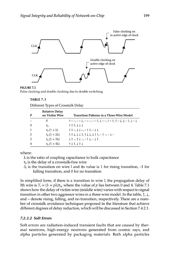
False clocking on
in active edge of clock
CLK
Double clocking on
active edge of clock
CLK
199
Signal Integrity and Reliability of Network-on-Chip
Figure 7.5
False clocking and double clocking due to double switching.
TABLe 7.1
Different Types of Crosstalk Delay
Relative Delay
P
on Victim Wire
Transition Patterns in a Three-Wire Model
–
0
↑ – –, – – ↓, – – –, – – ↑, ↓ – –, ↑ – ↑, ↑ – ↓, ↓ – ↑, ↓ – ↓
0
τ 0
↑ ↑ ↑, ↓ ↓ ↓
1
τ 0 (1 + λ)
↑ ↑ –, ↓ ↓ –, – ↑ ↑, – ↓ ↓
2
τ 0 (1 + 2λ)
↑ ↑ ↓, ↓ ↓ ↑, ↑ ↓ ↓, ↓ ↑ ↑, – ↑ –, – ↓ –
3
τ 0 (1 + 3λ)
↓ ↑ –, ↑ ↓ –, – ↑ ↓, – ↓ ↑
4
τ 0 (1 + 4λ)
↑ ↓ ↑, ↓ ↑ ↓
where:
λ is the ratio of coupling capacitance to bulk capacitance
τ 0 is the delay of a crosstalk-free wire
Δ l is the transition on wire l and its value is 1 for rising transition, –1 for
falling transition, and 0 for no transition
In simplified form, if there is a transition in wire l, the propagation delay of
lth wire is T l = (1 + pλ)τ 0 , where the value of p lies between 0 and 4. Table 7.1
shows how the delay of victim wire (middle wire) varies with respect to signal
transition in other two aggressor wires in a three-wire model. In the table, ↑, ↓,
and – denote rising, falling, and no transition, respectively. There are a number of crosstalk avoidance techniques proposed in the literature that achieve
different degrees of delay reduction, which will be discussed in Section 7.4.2.1.
7.2.3.2 Soft Errors
Soft errors are radiation-induced transient faults that are caused by thermal neutrons, high-energy neutrons generated from cosmic rays, and
alpha particles generated by packaging materials. Both alpha particles