

183
Low-Power Techniques for Network-on-Chip
6.4.2.2 DFS Algorithm
Given the link utilization, the DFS algorithm dynamically adapts its frequency to achieve power savings with minimal impact on performance.
It prescribes whether to increase clock frequency to higher level, decrease
clock frequency to lower level, or do nothing. Even though the link utilization estimator predicts correctly the workload, determining how fast to
run the network is nontrivial. The algorithm controlling DFS link trades off
power and performance. Intuitively, if a link utilization is high (Ψ L ≥ π u ),
the clock frequency will be increased. On the contrary, when link utilization falls below the threshold value (Ψ L < π l ), the clock frequency will
be reduced. The threshold values (π u and π l are the threshold values to
increase and decrease the frequency, respectively) can be set to a single
value for π u and π l for the simplest method. Also, multiple thresholds can
be set corresponding to each state (three sets of thresholds from π l1× to π l4×
and π u1× to π u4× ). In addition, threshold values can be predefined in design
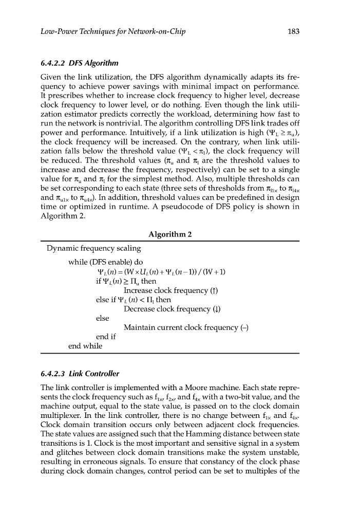
time or optimized in runtime. A pseudocode of DFS policy is shown in
Algorithm 2.
Algorithm 2
Dynamic frequency scaling
while (DFS enable) do
Ψ n = (W ×U L n + Ψ (n − ))/(
L ( )
( )
L
1
W + 1)
if Ψ L n
then
( ) ≥ Π u
Increase clock frequency (↑)
else if Ψ L n
( ) < Π l then
Decrease clock frequency (↓)
else
Maintain current clock frequency (–)
end if
end while
6.4.2.3 Link Controller
The link controller is implemented with a Moore machine. Each state represents the clock frequency such as f 1× , f 2× , and f 4× with a two-bit value, and the
machine output, equal to the state value, is passed on to the clock domain
multiplexer. In the link controller, there is no change between f 1× and f 4× .
Clock domain transition occurs only between adjacent clock frequencies.
The state values are assigned such that the Hamming distance between state
transitions is 1. Clock is the most important and sensitive signal in a system
and glitches between clock domain transitions make the system unstable,
resulting in erroneous signals. To ensure that constancy of the clock phase
during clock domain changes, control period can be set to multiples of the
Low-Power Techniques for Network-on-Chip
6.4.2.2 DFS Algorithm
Given the link utilization, the DFS algorithm dynamically adapts its frequency to achieve power savings with minimal impact on performance.
It prescribes whether to increase clock frequency to higher level, decrease
clock frequency to lower level, or do nothing. Even though the link utilization estimator predicts correctly the workload, determining how fast to
run the network is nontrivial. The algorithm controlling DFS link trades off
power and performance. Intuitively, if a link utilization is high (Ψ L ≥ π u ),
the clock frequency will be increased. On the contrary, when link utilization falls below the threshold value (Ψ L < π l ), the clock frequency will
be reduced. The threshold values (π u and π l are the threshold values to
increase and decrease the frequency, respectively) can be set to a single
value for π u and π l for the simplest method. Also, multiple thresholds can
be set corresponding to each state (three sets of thresholds from π l1× to π l4×
and π u1× to π u4× ). In addition, threshold values can be predefined in design
time or optimized in runtime. A pseudocode of DFS policy is shown in
Algorithm 2.
Algorithm 2
Dynamic frequency scaling
while (DFS enable) do
Ψ n = (W ×U L n + Ψ (n − ))/(
L ( )
( )
L
1
W + 1)
if Ψ L n
then
( ) ≥ Π u
Increase clock frequency (↑)
else if Ψ L n
( ) < Π l then
Decrease clock frequency (↓)
else
Maintain current clock frequency (–)
end if
end while
6.4.2.3 Link Controller
The link controller is implemented with a Moore machine. Each state represents the clock frequency such as f 1× , f 2× , and f 4× with a two-bit value, and the
machine output, equal to the state value, is passed on to the clock domain
multiplexer. In the link controller, there is no change between f 1× and f 4× .
Clock domain transition occurs only between adjacent clock frequencies.
The state values are assigned such that the Hamming distance between state
transitions is 1. Clock is the most important and sensitive signal in a system
and glitches between clock domain transitions make the system unstable,
resulting in erroneous signals. To ensure that constancy of the clock phase
during clock domain changes, control period can be set to multiples of the