

169
Low-Power Techniques for Network-on-Chip
i1
i0
invert
Output
Hamming
Input
D
Clr
Clk
Q
reset
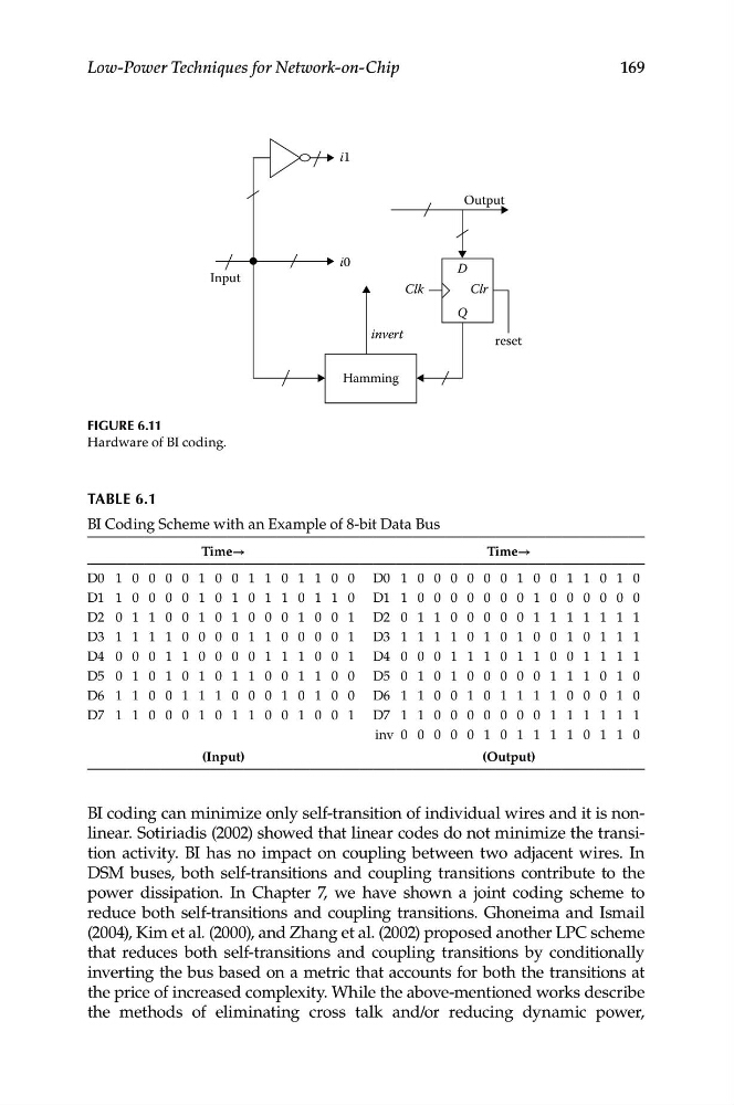
Figure 6.11
Hardware of BI coding.
TABLe 6.1
BI Coding Scheme with an Example of 8-bit Data Bus
Time→
Time→
D0 1 0 0 0 0 1 0 0 1 1 0 1 1 0 0 D0 1 0 0 0 0 0 0 1 0 0 1 1 0 1 0
D1 1 0 0 0 0 1 0 1 0 1 1 0 1 1 0 D1 1 0 0 0 0 0 0 0 1 0 0 0 0 0 0
D2 0 1 1 0 0 1 0 1 0 0 0 1 0 0 1 D2 0 1 1 0 0 0 0 0 1 1 1 1 1 1 1
D3 1 1 1 1 0 0 0 0 1 1 0 0 0 0 1 D3 1 1 1 1 0 1 0 1 0 0 1 0 1 1 1
D4 0 0 0 1 1 0 0 0 0 1 1 1 0 0 1 D4 0 0 0 1 1 1 0 1 1 0 0 1 1 1 1
D5 0 1 0 1 0 1 0 1 1 0 0 1 1 0 0 D5 0 1 0 1 0 0 0 0 0 1 1 1 0 1 0
D6 1 1 0 0 1 1 1 0 0 0 1 0 1 0 0 D6 1 1 0 0 1 0 1 1 1 1 0 0 0 1 0
D7 1 1 0 0 0 1 0 1 1 0 0 1 0 0 1 D7 1 1 0 0 0 0 0 0 0 1 1 1 1 1 1
inv 0 0 0 0 0 1 0 1 1 1 1 0 1 1 0
(Input)
(Output)
BI coding can minimize only self-transition of individual wires and it is nonlinear. Sotiriadis (2002) showed that linear codes do not minimize the transition activity. BI has no impact on coupling between two adjacent wires. In
DSM buses, both self-transitions and coupling transitions contribute to the
power dissipation. In Chapter 7, we have shown a joint coding scheme to
reduce both self-transitions and coupling transitions. Ghoneima and Ismail
(2004), Kim et al. (2000), and Zhang et al. (2002) proposed another LPC scheme
that reduces both self-transitions and coupling transitions by conditionally
inverting the bus based on a metric that accounts for both the transitions at
the price of increased complexity. While the above-mentioned works describe
the methods of eliminating cross talk and/or reducing dynamic power,