

⎡
dV n−1
dV n ⎤ V n
f
V n
i
C s
λ
+ (1+ λ) ×
× − ×
=
−
(6.5)
⎣ ⎢
dt
dt ⎦ ⎥ R k R k
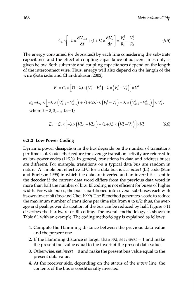
The energy consumed (or deposited) by each line considering the substrate
capacitance and the effect of coupling capacitance of adjacent lines only is
given below. Both substrate and coupling capacitances depend on the length
of the interconnect wire. Thus, energy will also depend on the length of the
wire (Sotiriadis and Chandrakasan 2002).
f
i
f
i
f
⎡
⎤
E 1 = C s × 1+ λ)× V 1 V 1 ) − × V 2 V 2 ) ⎦
× 1
(
( −
λ ( −
V
⎣
f
i
f
i
f
i
f
⎡ ⎡
⎤
E = C × − × V k
V −1 + ( + 2λ) × k V ) − × V k V +1 ⎦
× V k
k
s
λ ( −1 − k ) 1
( V − k λ ( +1 − k )
,
⎣
where k = , ,…, (n − )
2 3
1
f
i
f
i
f
⎡ λ
⎤
(6.6)
E n = C s × − × ( V n−1 − V n−1 ) + (1+ λ) × ( V n −V n ) ⎦
×V n
⎣
168
Network-on-Chip
6.3.2 Low-Power Coding
Dynamic power dissipation in the bus depends on the number of transitions
per time slot. Codes that reduce the average transition activity are referred to
as low-power codes (LPCs). In general, transitions in data and address buses
are different. For example, transitions on a typical data bus are random in
nature. A simple but effective LPC for a data bus is bus-invert (BI) code (Stan
and Burleson 1995) in which the data are inverted and an invert bit is sent to
the decoder if the current data word differs from the previous data word in
more than half the number of bits. BI coding is not efficient for buses of higher
width. For wide buses, the bus is partitioned into several sub-buses each with
its own invert bit (Yoo and Choi 1999). The BI method generates a code to reduce
the maximum number of transitions per time slot from n to n/2; thus, the average and peak power dissipation of the bus can be reduced by half. Figure 6.11
describes the hardware of BI coding. The overall methodology is shown in
Table 6.1 with an example. The coding methodology is explained as follows:
1. Compute the Hamming distance between the previous data value
and the present one.
2. If the Hamming distance is larger than n/2, set invert = 1 and make
the present bus value equal to the invert of the present data value.
3. Otherwise, set invert = 0 and make the present bus value equal to the
present data value.
4. At the receiver side, depending on the status of the invert line, the
contents of the bus is conditionally inverted.
dV n−1
dV n ⎤ V n
f
V n
i
C s
λ
+ (1+ λ) ×
× − ×
=
−
(6.5)
⎣ ⎢
dt
dt ⎦ ⎥ R k R k
The energy consumed (or deposited) by each line considering the substrate
capacitance and the effect of coupling capacitance of adjacent lines only is
given below. Both substrate and coupling capacitances depend on the length
of the interconnect wire. Thus, energy will also depend on the length of the
wire (Sotiriadis and Chandrakasan 2002).
f
i
f
i
f
⎡
⎤
E 1 = C s × 1+ λ)× V 1 V 1 ) − × V 2 V 2 ) ⎦
× 1
(
( −
λ ( −
V
⎣
f
i
f
i
f
i
f
⎡ ⎡
⎤
E = C × − × V k
V −1 + ( + 2λ) × k V ) − × V k V +1 ⎦
× V k
k
s
λ ( −1 − k ) 1
( V − k λ ( +1 − k )
,
⎣
where k = , ,…, (n − )
2 3
1
f
i
f
i
f
⎡ λ
⎤
(6.6)
E n = C s × − × ( V n−1 − V n−1 ) + (1+ λ) × ( V n −V n ) ⎦
×V n
⎣
168
Network-on-Chip
6.3.2 Low-Power Coding
Dynamic power dissipation in the bus depends on the number of transitions
per time slot. Codes that reduce the average transition activity are referred to
as low-power codes (LPCs). In general, transitions in data and address buses
are different. For example, transitions on a typical data bus are random in
nature. A simple but effective LPC for a data bus is bus-invert (BI) code (Stan
and Burleson 1995) in which the data are inverted and an invert bit is sent to
the decoder if the current data word differs from the previous data word in
more than half the number of bits. BI coding is not efficient for buses of higher
width. For wide buses, the bus is partitioned into several sub-buses each with
its own invert bit (Yoo and Choi 1999). The BI method generates a code to reduce
the maximum number of transitions per time slot from n to n/2; thus, the average and peak power dissipation of the bus can be reduced by half. Figure 6.11
describes the hardware of BI coding. The overall methodology is shown in
Table 6.1 with an example. The coding methodology is explained as follows:
1. Compute the Hamming distance between the previous data value
and the present one.
2. If the Hamming distance is larger than n/2, set invert = 1 and make
the present bus value equal to the invert of the present data value.
3. Otherwise, set invert = 0 and make the present bus value equal to the
present data value.
4. At the receiver side, depending on the status of the invert line, the
contents of the bus is conditionally inverted.