

157
Low-Power Techniques for Network-on-Chip
T is absolute temperature in Kelvin
q is electrical charge of electron = 1.6 × 10 –19 Coulomb
2. Gate-induced drain leakage current flows from drain to substrate
induced by high field effect in the drain caused by a high V DG. Gateinduced drain leakage current increases exponentially with increasing temperature and decreasing oxide thickness.
3. Gate leakage current flows directly from the gate through the oxide to
the substrate due to gate oxide tunneling and hot carrier injection.
It increases exponentially with decreasing oxide thickness. In previous technology nodes (130 nm and above), gate leakage current was
negligible, but starting from the 90-nm technology node, gate leakage can be comparable with subthreshold leakage current. In future
technology nodes (28 nm and below), high-k dielectric materials will
be needed to keep gate leakage under control.
4. Reverse-bias junction leakage current flows due to drift of minority carriers and generation of electron–hole pairs in the depletion regions.
Leakage power is greatly influenced by process, voltage, and temperature.
One of the well-known facts about the leakage current is its significantly
large variability due to manufacturing conditions and environmental variations. For the above reasons, leakage power can vary by orders of magnitude
for different chips manufactured with same design, and hence, a statistical
leakage model is necessary in the UDSM technology (Lu and Agarwal 2007).
In Chapter 4, we have shown that interconnect power consumes a very
significant portion of the total chip power. The interconnect power mostly
depends on the voltage swing, the driver size, the parasitic capacitance of the
wire per unit length, and the length of the wire, whereas IO power is mostly
considered as analog power.
The most effective way to reduce the dynamic power is to reduce V DD , but
the trouble is that it tends to reduce the drain-to-source current (I DS ) and hence
slower the speed. If we ignore velocity saturation and other subtle effects that
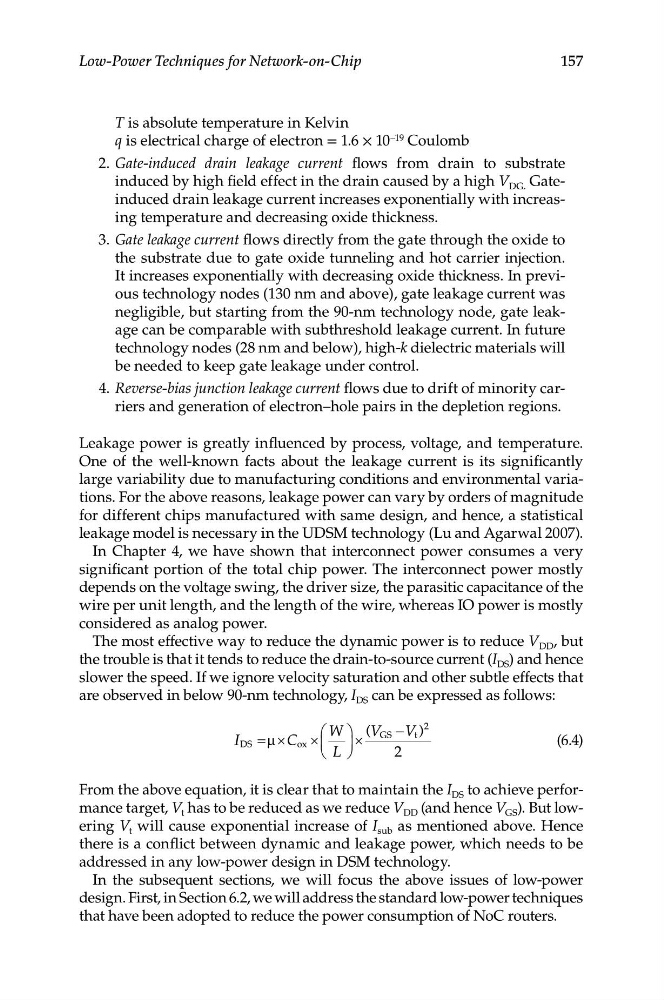
are observed in below 90-nm technology, I DS can be expressed as follows:
⎛ W
⎞ (V −V )
2
I
DS =µ ×
C o x ×
⎜ ⎟ ×
GS
t
(6.4)
⎝
L
⎠
2
From the above equation, it is clear that to maintain the I DS to achieve performance target, V t has to be reduced as we reduce V DD (and hence V GS ). But lowering V t will cause exponential increase of I sub as mentioned above. Hence
there is a conflict between dynamic and leakage power, which needs to be
addressed in any low-power design in DSM technology.
In the subsequent sections, we will focus the above issues of low-power
design. First, in Section 6.2, we will address the standard low-power techniques
that have been adopted to reduce the power consumption of NoC routers.
Low-Power Techniques for Network-on-Chip
T is absolute temperature in Kelvin
q is electrical charge of electron = 1.6 × 10 –19 Coulomb
2. Gate-induced drain leakage current flows from drain to substrate
induced by high field effect in the drain caused by a high V DG. Gateinduced drain leakage current increases exponentially with increasing temperature and decreasing oxide thickness.
3. Gate leakage current flows directly from the gate through the oxide to
the substrate due to gate oxide tunneling and hot carrier injection.
It increases exponentially with decreasing oxide thickness. In previous technology nodes (130 nm and above), gate leakage current was
negligible, but starting from the 90-nm technology node, gate leakage can be comparable with subthreshold leakage current. In future
technology nodes (28 nm and below), high-k dielectric materials will
be needed to keep gate leakage under control.
4. Reverse-bias junction leakage current flows due to drift of minority carriers and generation of electron–hole pairs in the depletion regions.
Leakage power is greatly influenced by process, voltage, and temperature.
One of the well-known facts about the leakage current is its significantly
large variability due to manufacturing conditions and environmental variations. For the above reasons, leakage power can vary by orders of magnitude
for different chips manufactured with same design, and hence, a statistical
leakage model is necessary in the UDSM technology (Lu and Agarwal 2007).
In Chapter 4, we have shown that interconnect power consumes a very
significant portion of the total chip power. The interconnect power mostly
depends on the voltage swing, the driver size, the parasitic capacitance of the
wire per unit length, and the length of the wire, whereas IO power is mostly
considered as analog power.
The most effective way to reduce the dynamic power is to reduce V DD , but
the trouble is that it tends to reduce the drain-to-source current (I DS ) and hence
slower the speed. If we ignore velocity saturation and other subtle effects that
are observed in below 90-nm technology, I DS can be expressed as follows:
⎛ W
⎞ (V −V )
2
I
DS =µ ×
C o x ×
⎜ ⎟ ×
GS
t
(6.4)
⎝
L
⎠
2
From the above equation, it is clear that to maintain the I DS to achieve performance target, V t has to be reduced as we reduce V DD (and hence V GS ). But lowering V t will cause exponential increase of I sub as mentioned above. Hence
there is a conflict between dynamic and leakage power, which needs to be
addressed in any low-power design in DSM technology.
In the subsequent sections, we will focus the above issues of low-power
design. First, in Section 6.2, we will address the standard low-power techniques
that have been adopted to reduce the power consumption of NoC routers.