

114
Network-on-Chip
TABLe 4.12
Silicon Area Required for Each Type of Router after Clock Gating
Type-1 Router
Type-2 Router
Type-3 Router
Networks
Position
Area (mm 2 )
Position
Area (mm 2 )
Position
Area (mm 2 )
Mesh-1
Center
0.331
Edge
0.242
Corner
0.220
Mesh-2
Center
0.400
Edge
0.318
Corner
0.263
BFT
Leaf
0.290
Stem
0.330
Root
0.080
MoT
Leaf
0.183
Stem
0.180
Root
0.080
TABLe 4.13
Area Overhead for 32- and 256-Core-Based NoCs
32 Cores
256 Cores
Overall Area
Overall Area
Networks
(mm 2 )
Overhead (%)
(mm 2 )
Overhead (%)
Mesh-1
247.47
23.74
1986.47
24.15
Mesh-2
226.79
13.40
1819.80
13.74
BFT
241.78
20.89
2018.02
26.13
MoT
247.7
23.85
2006.57
25.4
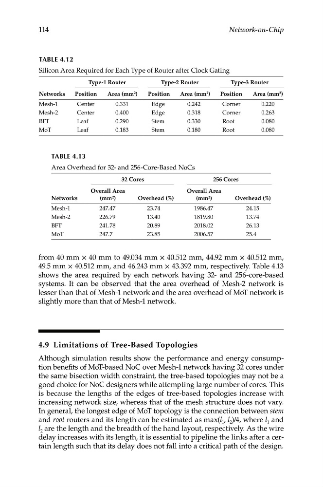
from 40 mm × 40 mm to 49.034 mm × 40.512 mm, 44.92 mm × 40.512 mm,
49.5 mm × 40.512 mm, and 46.243 mm × 43.392 mm, respectively. Table 4.13
shows the area required by each network having 32- and 256-core-based
systems. It can be observed that the area overhead of Mesh-2 network is
lesser than that of Mesh-1 network and the area overhead of MoT network is
slightly more than that of Mesh-1 network.
4.9 Limitations of Tree-Based Topologies
Although simulation results show the performance and energy consumption benefits of MoT-based NoC over Mesh-1 network having 32 cores under
the same bisection width constraint, the tree-based topologies may not be a
good choice for NoC designers while attempting large number of cores. This
is because the lengths of the edges of tree-based topologies increase with
increasing network size, whereas that of the mesh structure does not vary.
In general, the longest edge of MoT topology is the connection between stem
and root routers and its length can be estimated as max(l 1 , l 2 )/4, where l 1 and
l 2 are the length and the breadth of the hand layout, respectively. As the wire
delay increases with its length, it is essential to pipeline the links after a certain length such that its delay does not fall into a critical path of the design.