

398
N. Kumari et al.
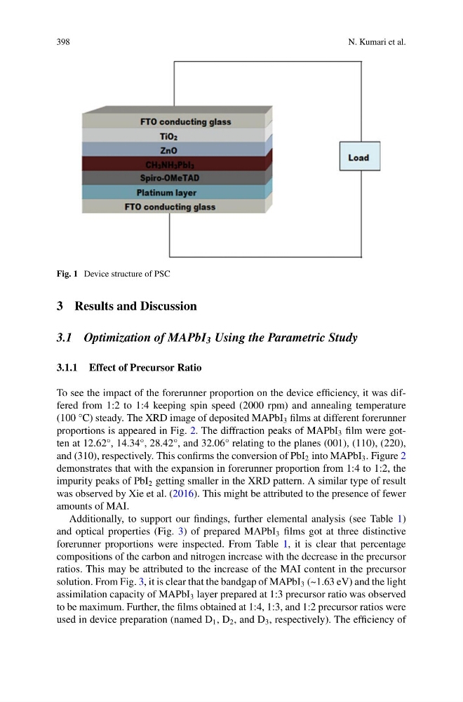
Fig. 1 Device structure of PSC
3 Results and Discussion
3.1 Optimization of MAPbI 3 Using the Parametric Study
3.1.1 Effect of Precursor Ratio
To see the impact of the forerunner proportion on the device efficiency, it was differed from 1:2 to 1:4 keeping spin speed (2000 rpm) and annealing temperature
(100 °C) steady. The XRD image of deposited MAPbI 3 films at different forerunner
proportions is appeared in Fig. 2. The diffraction peaks of MAPbI 3 film were gotten at 12.62°, 14.34°, 28.42°, and 32.06° relating to the planes (001), (110), (220),
and (310), respectively. This confirms the conversion of PbI 2 into MAPbI 3 . Figure 2
demonstrates that with the expansion in forerunner proportion from 1:4 to 1:2, the
impurity peaks of PbI 2 getting smaller in the XRD pattern. A similar type of result
was observed by Xie et al. (2016). This might be attributed to the presence of fewer
amounts of MAI.
Additionally, to support our findings, further elemental analysis (see Table 1)
and optical properties (Fig. 3) of prepared MAPbI 3 films got at three distinctive
forerunner proportions were inspected. From Table 1, it is clear that percentage
compositions of the carbon and nitrogen increase with the decrease in the precursor
ratios. This may be attributed to the increase of the MAI content in the precursor
solution. From Fig. 3, it is clear that the bandgap of MAPbI 3 (~1.63 eV) and the light
assimilation capacity of MAPbI 3 layer prepared at 1:3 precursor ratio was observed
to be maximum. Further, the films obtained at 1:4, 1:3, and 1:2 precursor ratios were
used in device preparation (named D 1 , D 2 , and D 3 , respectively). The efficiency of
N. Kumari et al.
Fig. 1 Device structure of PSC
3 Results and Discussion
3.1 Optimization of MAPbI 3 Using the Parametric Study
3.1.1 Effect of Precursor Ratio
To see the impact of the forerunner proportion on the device efficiency, it was differed from 1:2 to 1:4 keeping spin speed (2000 rpm) and annealing temperature
(100 °C) steady. The XRD image of deposited MAPbI 3 films at different forerunner
proportions is appeared in Fig. 2. The diffraction peaks of MAPbI 3 film were gotten at 12.62°, 14.34°, 28.42°, and 32.06° relating to the planes (001), (110), (220),
and (310), respectively. This confirms the conversion of PbI 2 into MAPbI 3 . Figure 2
demonstrates that with the expansion in forerunner proportion from 1:4 to 1:2, the
impurity peaks of PbI 2 getting smaller in the XRD pattern. A similar type of result
was observed by Xie et al. (2016). This might be attributed to the presence of fewer
amounts of MAI.
Additionally, to support our findings, further elemental analysis (see Table 1)
and optical properties (Fig. 3) of prepared MAPbI 3 films got at three distinctive
forerunner proportions were inspected. From Table 1, it is clear that percentage
compositions of the carbon and nitrogen increase with the decrease in the precursor
ratios. This may be attributed to the increase of the MAI content in the precursor
solution. From Fig. 3, it is clear that the bandgap of MAPbI 3 (~1.63 eV) and the light
assimilation capacity of MAPbI 3 layer prepared at 1:3 precursor ratio was observed
to be maximum. Further, the films obtained at 1:4, 1:3, and 1:2 precursor ratios were
used in device preparation (named D 1 , D 2 , and D 3 , respectively). The efficiency of