

62
S. Ghosh et al.
2.2 Parametric Representation of Precipitate Morphology and
Statistical Distributions
The morphology of the γ precipitate phase is generally quite complex that requires
a high dimensional shape representation. To avert surface profile representations
with large datasets, the order of the precipitate morphology representation is reduced
through parametric mapping functions with optimal number of parameters. Such
parametrization enables direct incorporation of the morphological parameters in
parametrically homogenized constitutive models [19, 20]. For each precipitate,
coefficients of the parametrized mapping function are calibrated via an orthogonal
distance minimization (ODM) algorithm [50], in which the 3D voxelization is
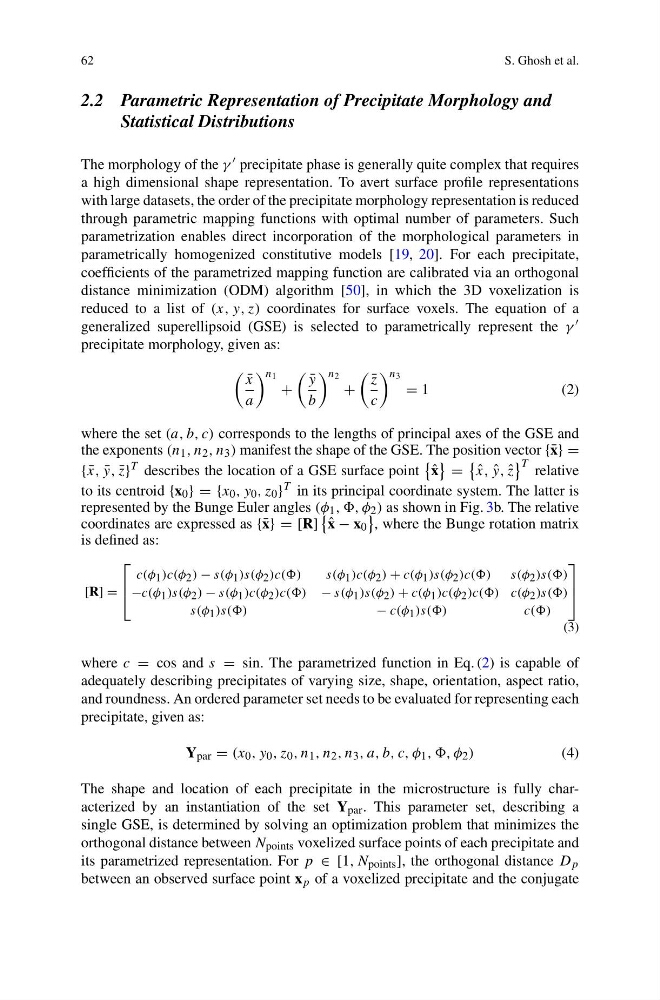
reduced to a list of (x, y, z) coordinates for surface voxels. The equation of a
generalized superellipsoid (GSE) is selected to parametrically represent the γ
precipitate morphology, given as:
¯
x
a
n 1
+
¯
y
b
n 2
+
¯
z
c
n 3
= 1
( 2 )
where the set (a, b, c) corresponds to the lengths of principal axes of the GSE and
the exponents (n 1 , n 2 , n 3 ) manifest the shape of the GSE. The position vector {¯ x} =
{ ¯
x, ¯
y, ¯
z}
T describes the location of a GSE surface point
ˆ
x
=
ˆ
x, ˆ
y, ˆ
z
T relative
to its centroid {x 0 } = {x 0 , y 0 , z 0 } T in its principal coordinate system. The latter is
represented by the Bunge Euler angles (φ 1 , ,, φ 2 ) as shown in Fig. 3b. The relative
coordinates are expressed as {¯ x} = [R]
ˆ
x − x 0
, where the Bunge rotation matrix
is defined as:
[R] =
⎡
⎢
⎣
c(φ 1 )c(φ 2 ) − s(φ 1 )s(φ 2 )c(()
s(φ 1 )c(φ 2 ) + c(φ 1 )s(φ 2 )c(() s(φ 2 )s(()
−c(φ 1 )s(φ 2 ) − s(φ 1 )c(φ 2 )c(() − s(φ 1 )s(φ 2 ) + c(φ 1 )c(φ 2 )c(() c(φ 2 )s(()
s(φ 1 )s(()
− c(φ 1 )s(()
c(()
⎤
⎥
⎦
(3)
where c = cos and s = sin. The parametrized function in Eq. (2) is capable of
adequately describing precipitates of varying size, shape, orientation, aspect ratio,
and roundness. An ordered parameter set needs to be evaluated for representing each
precipitate, given as:
Y par = (x 0 , y 0 , z 0 , n 1 , n 2 , n 3 , a, b, c, φ 1 , ,, φ 2 )
(4)
The shape and location of each precipitate in the microstructure is fully characterized by an instantiation of the set Y par . This parameter set, describing a
single GSE, is determined by solving an optimization problem that minimizes the
orthogonal distance between N points voxelized surface points of each precipitate and
its parametrized representation. For p ∈ [1, N points ], the orthogonal distance D p
between an observed surface point x p of a voxelized precipitate and the conjugate
S. Ghosh et al.
2.2 Parametric Representation of Precipitate Morphology and
Statistical Distributions
The morphology of the γ precipitate phase is generally quite complex that requires
a high dimensional shape representation. To avert surface profile representations
with large datasets, the order of the precipitate morphology representation is reduced
through parametric mapping functions with optimal number of parameters. Such
parametrization enables direct incorporation of the morphological parameters in
parametrically homogenized constitutive models [19, 20]. For each precipitate,
coefficients of the parametrized mapping function are calibrated via an orthogonal
distance minimization (ODM) algorithm [50], in which the 3D voxelization is
reduced to a list of (x, y, z) coordinates for surface voxels. The equation of a
generalized superellipsoid (GSE) is selected to parametrically represent the γ
precipitate morphology, given as:
¯
x
a
n 1
+
¯
y
b
n 2
+
¯
z
c
n 3
= 1
( 2 )
where the set (a, b, c) corresponds to the lengths of principal axes of the GSE and
the exponents (n 1 , n 2 , n 3 ) manifest the shape of the GSE. The position vector {¯ x} =
{ ¯
x, ¯
y, ¯
z}
T describes the location of a GSE surface point
ˆ
x
=
ˆ
x, ˆ
y, ˆ
z
T relative
to its centroid {x 0 } = {x 0 , y 0 , z 0 } T in its principal coordinate system. The latter is
represented by the Bunge Euler angles (φ 1 , ,, φ 2 ) as shown in Fig. 3b. The relative
coordinates are expressed as {¯ x} = [R]
ˆ
x − x 0
, where the Bunge rotation matrix
is defined as:
[R] =
⎡
⎢
⎣
c(φ 1 )c(φ 2 ) − s(φ 1 )s(φ 2 )c(()
s(φ 1 )c(φ 2 ) + c(φ 1 )s(φ 2 )c(() s(φ 2 )s(()
−c(φ 1 )s(φ 2 ) − s(φ 1 )c(φ 2 )c(() − s(φ 1 )s(φ 2 ) + c(φ 1 )c(φ 2 )c(() c(φ 2 )s(()
s(φ 1 )s(()
− c(φ 1 )s(()
c(()
⎤
⎥
⎦
(3)
where c = cos and s = sin. The parametrized function in Eq. (2) is capable of
adequately describing precipitates of varying size, shape, orientation, aspect ratio,
and roundness. An ordered parameter set needs to be evaluated for representing each
precipitate, given as:
Y par = (x 0 , y 0 , z 0 , n 1 , n 2 , n 3 , a, b, c, φ 1 , ,, φ 2 )
(4)
The shape and location of each precipitate in the microstructure is fully characterized by an instantiation of the set Y par . This parameter set, describing a
single GSE, is determined by solving an optimization problem that minimizes the
orthogonal distance between N points voxelized surface points of each precipitate and
its parametrized representation. For p ∈ [1, N points ], the orthogonal distance D p
between an observed surface point x p of a voxelized precipitate and the conjugate