

Geometric Modeling of Transverse Cracking of Composites
361
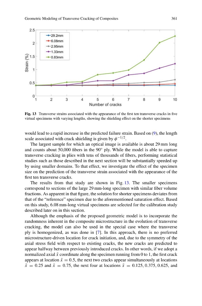
Fig. 13 Transverse strains associated with the appearance of the first ten transverse cracks in five
virtual specimens with varying lengths, showing the shielding effect on the shorter specimens
would lead to a rapid increase in the predicted failure strain. Based on (9), the length
scale associated with crack shielding is given by φ −1/2 .
The largest sample for which an optical image is available is about 29 mm long
and counts about 50,000 fibers in the 90 ◦ ply. While the model is able to capture
transverse cracking in plies with tens of thousands of fibers, performing statistical
studies such as those described in the next section will be substantially speeded up
by using smaller domains. To that effect, we investigate the effect of the specimen
size on the prediction of the transverse strain associated with the appearance of the
first ten transverse cracks.
The results from that study are shown in Fig. 13. The smaller specimens
correspond to sections of the large 29 mm-long specimen with similar fiber volume
fractions. As apparent in that figure, the solution for shorter specimens deviates from
that of the “reference” specimen due to the aforementioned saturation effect. Based
on this study, 6.08 mm-long virtual specimens are selected for the calibration study
described later on in this section.
Although the emphasis of the proposed geometric model is to incorporate the
randomness inherent in the composite microstructure in the evolution of transverse
cracking, the model can also be used in the special case where the transverse
ply is homogenized, as was done in [7]. In this approach, there is no preferred
microstructure-driven location for crack initiation, and, due to the symmetry of the
axial stress field with respect to existing cracks, the new cracks are predicted to
appear halfway between previously introduced cracks. In other words, if we adopt a
normalized axial ˜
x coordinate along the specimen running from 0 to 1, the first crack
appears at location ˜
x = 0.5, the next two cracks appear simultaneously at locations
˜
x = 0.25 and ˜
x = 0.75, the next four at locations ˜
x = 0.125, 0.375, 0.625, and
361
Fig. 13 Transverse strains associated with the appearance of the first ten transverse cracks in five
virtual specimens with varying lengths, showing the shielding effect on the shorter specimens
would lead to a rapid increase in the predicted failure strain. Based on (9), the length
scale associated with crack shielding is given by φ −1/2 .
The largest sample for which an optical image is available is about 29 mm long
and counts about 50,000 fibers in the 90 ◦ ply. While the model is able to capture
transverse cracking in plies with tens of thousands of fibers, performing statistical
studies such as those described in the next section will be substantially speeded up
by using smaller domains. To that effect, we investigate the effect of the specimen
size on the prediction of the transverse strain associated with the appearance of the
first ten transverse cracks.
The results from that study are shown in Fig. 13. The smaller specimens
correspond to sections of the large 29 mm-long specimen with similar fiber volume
fractions. As apparent in that figure, the solution for shorter specimens deviates from
that of the “reference” specimen due to the aforementioned saturation effect. Based
on this study, 6.08 mm-long virtual specimens are selected for the calibration study
described later on in this section.
Although the emphasis of the proposed geometric model is to incorporate the
randomness inherent in the composite microstructure in the evolution of transverse
cracking, the model can also be used in the special case where the transverse
ply is homogenized, as was done in [7]. In this approach, there is no preferred
microstructure-driven location for crack initiation, and, due to the symmetry of the
axial stress field with respect to existing cracks, the new cracks are predicted to
appear halfway between previously introduced cracks. In other words, if we adopt a
normalized axial ˜
x coordinate along the specimen running from 0 to 1, the first crack
appears at location ˜
x = 0.5, the next two cracks appear simultaneously at locations
˜
x = 0.25 and ˜
x = 0.75, the next four at locations ˜
x = 0.125, 0.375, 0.625, and