

Geometric Modeling of Transverse Cracking of Composites
359
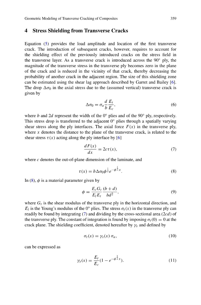
4 Stress Shielding from Transverse Cracks
Equation (5) provides the load amplitude and location of the first transverse
crack. The introduction of subsequent cracks, however, requires to account for
the shielding effect of the previously introduced cracks on the stress field in
the transverse layer. As a transverse crack is introduced across the 90 ◦ ply, the
magnitude of the transverse stress in the transverse ply becomes zero in the plane
of the crack and is reduced in the vicinity of that crack, thereby decreasing the
probability of another crack in the adjacent region. The size of this shielding zone
can be estimated using the shear lag approach described by Garret and Bailey [6].
The drop σ 0 in the axial stress due to the (assumed vertical) transverse crack is
given by
σ 0 = σ a
d
b
E t
E c
,
(6)
where b and 2d represent the width of the 0 ◦ plies and of the 90 ◦ ply, respectively.
This stress drop is transferred to the adjacent 0 ◦ plies through a spatially varying
shear stress along the ply interfaces. The axial force F (x) in the transverse ply,
where x denotes the distance to the plane of the transverse crack, is related to the
shear stress τ (x) acting along the ply interface by [6]
dF (x)
dx
= 2cτ (x),
(7)
where c denotes the out-of-plane dimension of the laminate, and
τ (x) = bbσ 0 φ
1
2 e
−φ
1
2 x .
(8)
In (8), φ is a material parameter given by
φ =
E c G t
E l E t
(b + d)
bd 2 ,
(9)
where G t is the shear modulus of the transverse ply in the horizontal direction, and
E l is the Young’s modulus of the 0 ◦ plies. The stress σ t (x) in the transverse ply can
readily be found by integrating (7) and dividing by the cross-sectional area (2cd) of
the transverse ply. The constant of integration is found by imposing σ t (0) = 0 at the
crack plane. The shielding coefficient, denoted hereafter by γ s and defined by
σ t (x) = γ s (x) σ a ,
(10)
can be expressed as
γ s (x) =
E t
E c
(1 − e
−φ
1
2 x ).
(11)
359
4 Stress Shielding from Transverse Cracks
Equation (5) provides the load amplitude and location of the first transverse
crack. The introduction of subsequent cracks, however, requires to account for
the shielding effect of the previously introduced cracks on the stress field in
the transverse layer. As a transverse crack is introduced across the 90 ◦ ply, the
magnitude of the transverse stress in the transverse ply becomes zero in the plane
of the crack and is reduced in the vicinity of that crack, thereby decreasing the
probability of another crack in the adjacent region. The size of this shielding zone
can be estimated using the shear lag approach described by Garret and Bailey [6].
The drop σ 0 in the axial stress due to the (assumed vertical) transverse crack is
given by
σ 0 = σ a
d
b
E t
E c
,
(6)
where b and 2d represent the width of the 0 ◦ plies and of the 90 ◦ ply, respectively.
This stress drop is transferred to the adjacent 0 ◦ plies through a spatially varying
shear stress along the ply interfaces. The axial force F (x) in the transverse ply,
where x denotes the distance to the plane of the transverse crack, is related to the
shear stress τ (x) acting along the ply interface by [6]
dF (x)
dx
= 2cτ (x),
(7)
where c denotes the out-of-plane dimension of the laminate, and
τ (x) = bbσ 0 φ
1
2 e
−φ
1
2 x .
(8)
In (8), φ is a material parameter given by
φ =
E c G t
E l E t
(b + d)
bd 2 ,
(9)
where G t is the shear modulus of the transverse ply in the horizontal direction, and
E l is the Young’s modulus of the 0 ◦ plies. The stress σ t (x) in the transverse ply can
readily be found by integrating (7) and dividing by the cross-sectional area (2cd) of
the transverse ply. The constant of integration is found by imposing σ t (0) = 0 at the
crack plane. The shielding coefficient, denoted hereafter by γ s and defined by
σ t (x) = γ s (x) σ a ,
(10)
can be expressed as
γ s (x) =
E t
E c
(1 − e
−φ
1
2 x ).
(11)