

358
A. Agrawal et al.
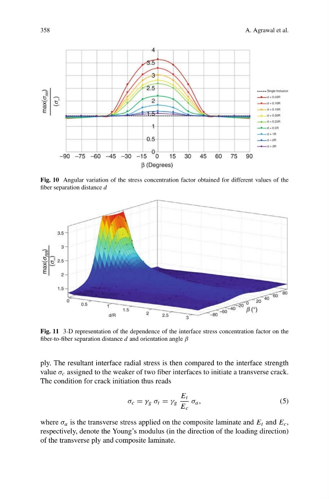
Fig. 10 Angular variation of the stress concentration factor obtained for different values of the
fiber separation distance d
Fig. 11 3-D representation of the dependence of the interface stress concentration factor on the
fiber-to-fiber separation distance d and orientation angle β
ply. The resultant interface radial stress is then compared to the interface strength
value σ c assigned to the weaker of two fiber interfaces to initiate a transverse crack.
The condition for crack initiation thus reads
σ c = γ g σ t = γ g
E t
E c
σ a ,
(5)
where σ a is the transverse stress applied on the composite laminate and E t and E c ,
respectively, denote the Young’s modulus (in the direction of the loading direction)
of the transverse ply and composite laminate.
A. Agrawal et al.
Fig. 10 Angular variation of the stress concentration factor obtained for different values of the
fiber separation distance d
Fig. 11 3-D representation of the dependence of the interface stress concentration factor on the
fiber-to-fiber separation distance d and orientation angle β
ply. The resultant interface radial stress is then compared to the interface strength
value σ c assigned to the weaker of two fiber interfaces to initiate a transverse crack.
The condition for crack initiation thus reads
σ c = γ g σ t = γ g
E t
E c
σ a ,
(5)
where σ a is the transverse stress applied on the composite laminate and E t and E c ,
respectively, denote the Young’s modulus (in the direction of the loading direction)
of the transverse ply and composite laminate.