

Geometric Modeling of Transverse Cracking of Composites
353
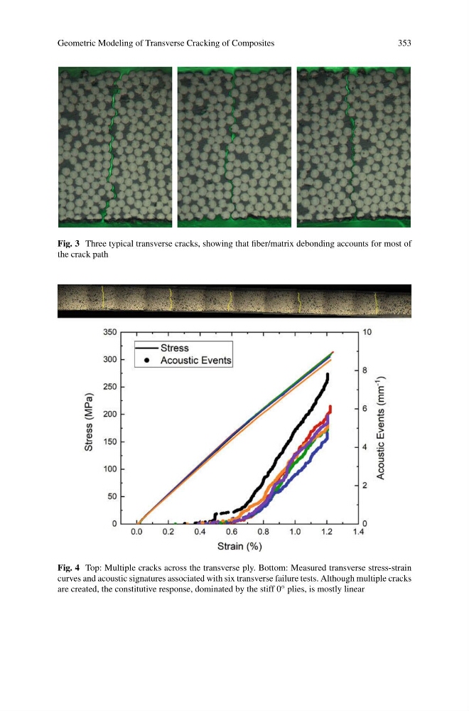
Fig. 3 Three typical transverse cracks, showing that fiber/matrix debonding accounts for most of
the crack path
Fig. 4 Top: Multiple cracks across the transverse ply. Bottom: Measured transverse stress-strain
curves and acoustic signatures associated with six transverse failure tests. Although multiple cracks
are created, the constitutive response, dominated by the stiff 0 ◦ plies, is mostly linear
353
Fig. 3 Three typical transverse cracks, showing that fiber/matrix debonding accounts for most of
the crack path
Fig. 4 Top: Multiple cracks across the transverse ply. Bottom: Measured transverse stress-strain
curves and acoustic signatures associated with six transverse failure tests. Although multiple cracks
are created, the constitutive response, dominated by the stiff 0 ◦ plies, is mostly linear