

334
S. Zacek et al.
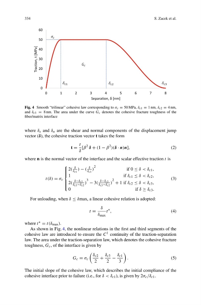
Fig. 4 Smooth “trilinear” cohesive law corresponding to σ c = 50 MPa, δ c1 = 1 nm, δ c2 = 4 nm,
and δ c3 = 8 nm. The area under the curve G c denotes the cohesive fracture toughness of the
fiber/matrix interface
where δ s and δ n are the shear and normal components of the displacement jump
vector (δ), the cohesive traction vector t takes the form
t =
t
δ
[β
2 δ + (1 − β
2 )(δ · n)n],
(2)
where n is the normal vector of the interface and the scalar effective traction t is
t (δ) = σ c
⎧
⎪ ⎪ ⎪ ⎨
⎪ ⎪ ⎪ ⎩
2(
δ
δ c1
) − (
δ
δ c1
)
2
if 0 ≤ δ < δ c1 ,
1
i f δ c1 ≤ δ < δ c2 ,
2(
δ−δ c2
δ c3 −δ c2
)
3 − 3(
δ−δ c2
δ c3 −δ c2
)
2 + 1 if δ c2 ≤ δ < δ c3 ,
0
i f δ ≥ δ c3 .
(3)
For unloading, when δ ≤ δmax, a linear cohesive relation is adopted:
t =
δ
δ max
t
∗ ,
(4)
where t ∗ = t (δ max ).
As shown in Fig. 4, the nonlinear relations in the first and third segments of the
cohesive law are introduced to ensure the C 1 continuity of the traction-separation
law. The area under the traction-separation law, which denotes the cohesive fracture
toughness, G c , of the interface is given by
G c = σ c
δ c2
2
+
δ c3
2
−
δ c1
3
.
(5)
The initial slope of the cohesive law, which describes the initial compliance of the
cohesive interface prior to failure (i.e., for δ < δ c1 ), is given by 2σ c /δ c1 .
S. Zacek et al.
Fig. 4 Smooth “trilinear” cohesive law corresponding to σ c = 50 MPa, δ c1 = 1 nm, δ c2 = 4 nm,
and δ c3 = 8 nm. The area under the curve G c denotes the cohesive fracture toughness of the
fiber/matrix interface
where δ s and δ n are the shear and normal components of the displacement jump
vector (δ), the cohesive traction vector t takes the form
t =
t
δ
[β
2 δ + (1 − β
2 )(δ · n)n],
(2)
where n is the normal vector of the interface and the scalar effective traction t is
t (δ) = σ c
⎧
⎪ ⎪ ⎪ ⎨
⎪ ⎪ ⎪ ⎩
2(
δ
δ c1
) − (
δ
δ c1
)
2
if 0 ≤ δ < δ c1 ,
1
i f δ c1 ≤ δ < δ c2 ,
2(
δ−δ c2
δ c3 −δ c2
)
3 − 3(
δ−δ c2
δ c3 −δ c2
)
2 + 1 if δ c2 ≤ δ < δ c3 ,
0
i f δ ≥ δ c3 .
(3)
For unloading, when δ ≤ δmax, a linear cohesive relation is adopted:
t =
δ
δ max
t
∗ ,
(4)
where t ∗ = t (δ max ).
As shown in Fig. 4, the nonlinear relations in the first and third segments of the
cohesive law are introduced to ensure the C 1 continuity of the traction-separation
law. The area under the traction-separation law, which denotes the cohesive fracture
toughness, G c , of the interface is given by
G c = σ c
δ c2
2
+
δ c3
2
−
δ c1
3
.
(5)
The initial slope of the cohesive law, which describes the initial compliance of the
cohesive interface prior to failure (i.e., for δ < δ c1 ), is given by 2σ c /δ c1 .