

Transverse Failure of Unidirectional Composites: Sensitivity to Interfacial Properties
333
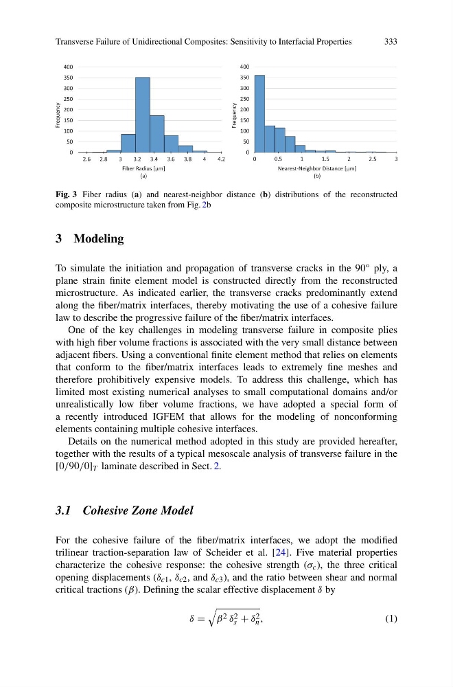
Fig. 3 Fiber radius (a) and nearest-neighbor distance (b) distributions of the reconstructed
composite microstructure taken from Fig. 2b
3 Modeling
To simulate the initiation and propagation of transverse cracks in the 90 ◦ ply, a
plane strain finite element model is constructed directly from the reconstructed
microstructure. As indicated earlier, the transverse cracks predominantly extend
along the fiber/matrix interfaces, thereby motivating the use of a cohesive failure
law to describe the progressive failure of the fiber/matrix interfaces.
One of the key challenges in modeling transverse failure in composite plies
with high fiber volume fractions is associated with the very small distance between
adjacent fibers. Using a conventional finite element method that relies on elements
that conform to the fiber/matrix interfaces leads to extremely fine meshes and
therefore prohibitively expensive models. To address this challenge, which has
limited most existing numerical analyses to small computational domains and/or
unrealistically low fiber volume fractions, we have adopted a special form of
a recently introduced IGFEM that allows for the modeling of nonconforming
elements containing multiple cohesive interfaces.
Details on the numerical method adopted in this study are provided hereafter,
together with the results of a typical mesoscale analysis of transverse failure in the
[0/90/0] T laminate described in Sect. 2.
3.1 Cohesive Zone Model
For the cohesive failure of the fiber/matrix interfaces, we adopt the modified
trilinear traction-separation law of Scheider et al. [24]. Five material properties
characterize the cohesive response: the cohesive strength (σ c ), the three critical
opening displacements (δ c1 , δ c2 , and δ c3 ), and the ratio between shear and normal
critical tractions (β). Defining the scalar effective displacement δ by
δ =
β 2 δ 2
s + δ 2
n ,
(1)
333
Fig. 3 Fiber radius (a) and nearest-neighbor distance (b) distributions of the reconstructed
composite microstructure taken from Fig. 2b
3 Modeling
To simulate the initiation and propagation of transverse cracks in the 90 ◦ ply, a
plane strain finite element model is constructed directly from the reconstructed
microstructure. As indicated earlier, the transverse cracks predominantly extend
along the fiber/matrix interfaces, thereby motivating the use of a cohesive failure
law to describe the progressive failure of the fiber/matrix interfaces.
One of the key challenges in modeling transverse failure in composite plies
with high fiber volume fractions is associated with the very small distance between
adjacent fibers. Using a conventional finite element method that relies on elements
that conform to the fiber/matrix interfaces leads to extremely fine meshes and
therefore prohibitively expensive models. To address this challenge, which has
limited most existing numerical analyses to small computational domains and/or
unrealistically low fiber volume fractions, we have adopted a special form of
a recently introduced IGFEM that allows for the modeling of nonconforming
elements containing multiple cohesive interfaces.
Details on the numerical method adopted in this study are provided hereafter,
together with the results of a typical mesoscale analysis of transverse failure in the
[0/90/0] T laminate described in Sect. 2.
3.1 Cohesive Zone Model
For the cohesive failure of the fiber/matrix interfaces, we adopt the modified
trilinear traction-separation law of Scheider et al. [24]. Five material properties
characterize the cohesive response: the cohesive strength (σ c ), the three critical
opening displacements (δ c1 , δ c2 , and δ c3 ), and the ratio between shear and normal
critical tractions (β). Defining the scalar effective displacement δ by
δ =
β 2 δ 2
s + δ 2
n ,
(1)