

SERVE-Boundary Conditions
313
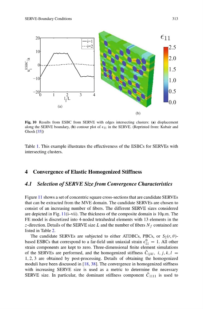
Fig. 10 Results from ESBC from SERVE with edges intersecting clusters: (a) displacement
along the SERVE boundary, (b) contour plot of 11 in the SERVE. (Reprinted from: Kubair and
Ghosh [35])
Table 1. This example illustrates the effectiveness of the ESBCs for SERVEs with
intersecting clusters.
4 Convergence of Elastic Homogenized Stiffness
4.1 Selection of SERVE Size from Convergence Characteristics
Figure 11 shows a set of concentric square cross-sections that are candidate SERVEs
that can be extracted from the MVE domain. The candidate SERVEs are chosen to
consist of an increasing number of fibers. The different SERVE sizes considered
are depicted in Fig. 11(i–vii). The thickness of the composite domain is 10μm. The
FE model is discretized into 4-noded tetrahedral elements with 13 elements in the
z-direction. Details of the SERVE size L and the number of fibers N f contained are
listed in Table 2.
The candidate SERVEs are subjected to either ATDBCs, PBCs, or S 2 (r, θ )based ESBCs that correspond to a far-field unit uniaxial strain 0
11 = 1. All other
strain components are kept to zero. Three-dimensional finite element simulations
of the SERVEs are performed, and the homogenized stiffness ¯
C ij kl , i, j, k, l =
1, 2, 3 are obtained by post-processing. Details of obtaining the homogenized
moduli have been discussed in [18, 38]. The convergence in homogenized stiffness
with increasing SERVE size is used as a metric to determine the necessary
SERVE size. In particular, the dominant stiffness component ¯
C 1111 is used to
313
Fig. 10 Results from ESBC from SERVE with edges intersecting clusters: (a) displacement
along the SERVE boundary, (b) contour plot of 11 in the SERVE. (Reprinted from: Kubair and
Ghosh [35])
Table 1. This example illustrates the effectiveness of the ESBCs for SERVEs with
intersecting clusters.
4 Convergence of Elastic Homogenized Stiffness
4.1 Selection of SERVE Size from Convergence Characteristics
Figure 11 shows a set of concentric square cross-sections that are candidate SERVEs
that can be extracted from the MVE domain. The candidate SERVEs are chosen to
consist of an increasing number of fibers. The different SERVE sizes considered
are depicted in Fig. 11(i–vii). The thickness of the composite domain is 10μm. The
FE model is discretized into 4-noded tetrahedral elements with 13 elements in the
z-direction. Details of the SERVE size L and the number of fibers N f contained are
listed in Table 2.
The candidate SERVEs are subjected to either ATDBCs, PBCs, or S 2 (r, θ )based ESBCs that correspond to a far-field unit uniaxial strain 0
11 = 1. All other
strain components are kept to zero. Three-dimensional finite element simulations
of the SERVEs are performed, and the homogenized stiffness ¯
C ij kl , i, j, k, l =
1, 2, 3 are obtained by post-processing. Details of obtaining the homogenized
moduli have been discussed in [18, 38]. The convergence in homogenized stiffness
with increasing SERVE size is used as a metric to determine the necessary
SERVE size. In particular, the dominant stiffness component ¯
C 1111 is used to