

430
Compact Models for Integrated Circuit Design
A typical model card includes separate subsections describing (1) general
information of the contents and usage of the model card, (2) process corners to model the device and circuit performance variability due to process
variability, and finally (3) the properly parameterized model parameters to
simulate different performance corners as discussed next.
12.2.4.1 Modeling Systematic Process Variability
Modeling process variation is critical in advanced ICs to design variability-aware VLSI circuits and IC chips [6–9]. The detailed modeling of process variability is described in Chapter 8 including the selection of process
0.00
0.20
0.40
0.60
0.80
1.00
1.4e−3
1.2e−3
1.0e−3
8.0e−4
6.0e−4
4.0e−4
0.0e+00
2.0e−4
(c)
V gs (V)
I
d (A)
Max error = 3.03%
W/L/T = 1./2.6e-002/25. V ds = 0.90V:1:I d − V gs
RMS error = 1.49%
0.00
0.20
0.40
0.60
0.80
1.00
1.0e−03
1.0e−04
1.0e−05
1.0e−06
1.0e−07
1.0e−08
1.0e−10
1.0e−09
(d)
V gs (V)
I
d (A)
Max error = 3.03%
W/L/T = 1./2.6e-002/25. V ds = 0.90V:1:I d − V gs
RMS error = 1.49%
0.30
−0.30
0.00
−0.60
V bs (V) =
0.30
−0.30
0.00
−0.60
V bs (V) =
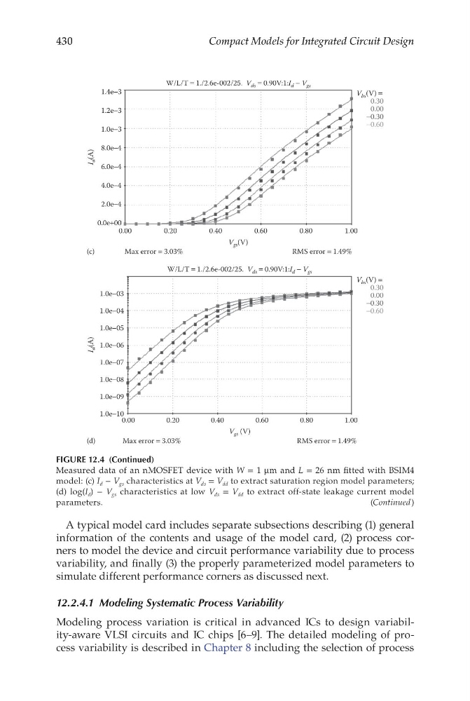
FIGURE 12.4 (Continued)
Measured data of an nMOSFET device with W = 1 μm and L = 26 nm fitted with BSIM4
model: (c) I d − V gs characteristics at V ds = V dd to extract saturation region model parameters;
(d) log(I d ) − V gs characteristics at low V ds = V dd to extract off-state leakage current model
parameters.
(Continued)
Compact Models for Integrated Circuit Design
A typical model card includes separate subsections describing (1) general
information of the contents and usage of the model card, (2) process corners to model the device and circuit performance variability due to process
variability, and finally (3) the properly parameterized model parameters to
simulate different performance corners as discussed next.
12.2.4.1 Modeling Systematic Process Variability
Modeling process variation is critical in advanced ICs to design variability-aware VLSI circuits and IC chips [6–9]. The detailed modeling of process variability is described in Chapter 8 including the selection of process
0.00
0.20
0.40
0.60
0.80
1.00
1.4e−3
1.2e−3
1.0e−3
8.0e−4
6.0e−4
4.0e−4
0.0e+00
2.0e−4
(c)
V gs (V)
I
d (A)
Max error = 3.03%
W/L/T = 1./2.6e-002/25. V ds = 0.90V:1:I d − V gs
RMS error = 1.49%
0.00
0.20
0.40
0.60
0.80
1.00
1.0e−03
1.0e−04
1.0e−05
1.0e−06
1.0e−07
1.0e−08
1.0e−10
1.0e−09
(d)
V gs (V)
I
d (A)
Max error = 3.03%
W/L/T = 1./2.6e-002/25. V ds = 0.90V:1:I d − V gs
RMS error = 1.49%
0.30
−0.30
0.00
−0.60
V bs (V) =
0.30
−0.30
0.00
−0.60
V bs (V) =
FIGURE 12.4 (Continued)
Measured data of an nMOSFET device with W = 1 μm and L = 26 nm fitted with BSIM4
model: (c) I d − V gs characteristics at V ds = V dd to extract saturation region model parameters;
(d) log(I d ) − V gs characteristics at low V ds = V dd to extract off-state leakage current model
parameters.
(Continued)