

429
Compact Model Library for Circuit Simulation
12.2.4 Generation of Compact Model Library
The parameter files for both NMOS and PMOS devices obtained by fitting
device characteristics with the target model (e.g., BSIM4) are assembled
together to form the model card. A typical industry standard compact model
library consists of a set of model cards that include logic with performance
options, analog/RF, and SRAM as well as interconnect models. In this chapter, we describe the methodology to generate a simple compact MOSFET
model that includes the real-device effects and process variability for device
analysis in circuit CAD. To illustrate the methodology to generate compact model library, examples of a MOSFET and an SRAM model cards are
presented in section, Sample Model Cards at the end of this chapter.
0.00
0.20
0.40
0.60
0.30
−0.30
0.00
−0.60
0.80
1.00
3.0e−4
2.5e−4
2.0e−4
1.5e−4
1.0e−4
5.0e−5
0.0e+00
(a)
V gs (V)
I
d (A)
Max error = 1.87%
W/L/T = 1./2.6e-002/25. V ds = 0.05V:0:I d − V gs
RMS error = 0.74%
V bs (V) =
0.00
0.20
0.40
0.60
0.30
−0.30
0.00
−0.60
0.80
1.00
1.0e−03
1.0e−04
1.0e−05
1.0e−06
1.0e−07
1.0e−08
1.0e−09
1.0e−10
1.0e−11
(b)
V gs (V)
I
d (A)
Max error = 1.87%
W/L/T = 1./2.6e-002/25. V ds = 0.05V:0:I d − V gs
RMS error = 0.74%
V bs (V) =
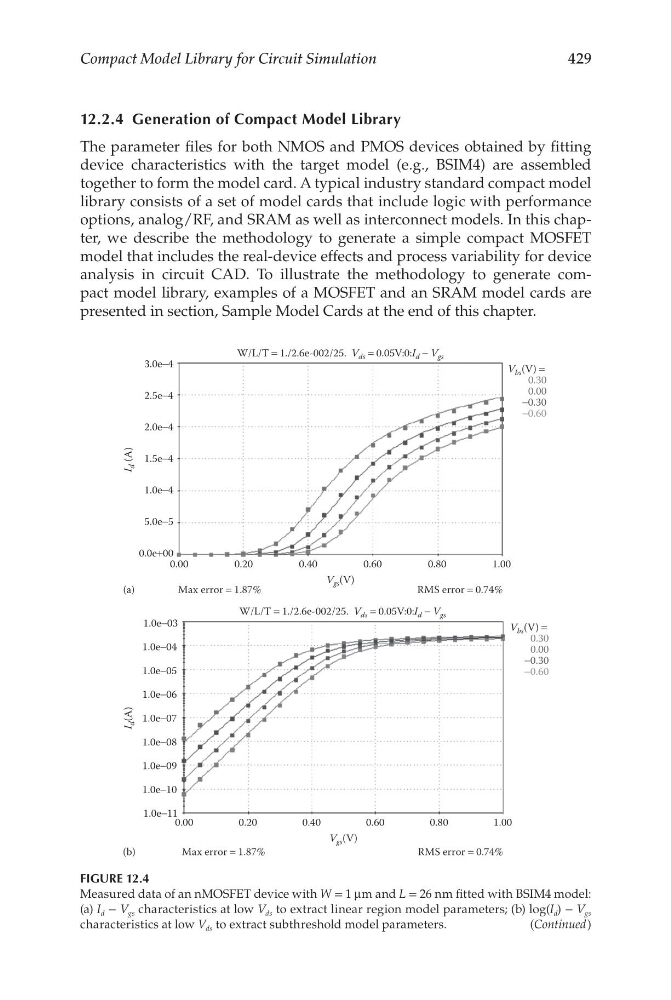
FIGURE 12.4
Measured data of an nMOSFET device with W = 1 μm and L = 26 nm fitted with BSIM4 model:
(a) I d − V gs characteristics at low V ds to extract linear region model parameters; (b) log(I d ) − V gs
characteristics at low V ds to extract subthreshold model parameters.
(Continued)
Compact Model Library for Circuit Simulation
12.2.4 Generation of Compact Model Library
The parameter files for both NMOS and PMOS devices obtained by fitting
device characteristics with the target model (e.g., BSIM4) are assembled
together to form the model card. A typical industry standard compact model
library consists of a set of model cards that include logic with performance
options, analog/RF, and SRAM as well as interconnect models. In this chapter, we describe the methodology to generate a simple compact MOSFET
model that includes the real-device effects and process variability for device
analysis in circuit CAD. To illustrate the methodology to generate compact model library, examples of a MOSFET and an SRAM model cards are
presented in section, Sample Model Cards at the end of this chapter.
0.00
0.20
0.40
0.60
0.30
−0.30
0.00
−0.60
0.80
1.00
3.0e−4
2.5e−4
2.0e−4
1.5e−4
1.0e−4
5.0e−5
0.0e+00
(a)
V gs (V)
I
d (A)
Max error = 1.87%
W/L/T = 1./2.6e-002/25. V ds = 0.05V:0:I d − V gs
RMS error = 0.74%
V bs (V) =
0.00
0.20
0.40
0.60
0.30
−0.30
0.00
−0.60
0.80
1.00
1.0e−03
1.0e−04
1.0e−05
1.0e−06
1.0e−07
1.0e−08
1.0e−09
1.0e−10
1.0e−11
(b)
V gs (V)
I
d (A)
Max error = 1.87%
W/L/T = 1./2.6e-002/25. V ds = 0.05V:0:I d − V gs
RMS error = 0.74%
V bs (V) =
FIGURE 12.4
Measured data of an nMOSFET device with W = 1 μm and L = 26 nm fitted with BSIM4 model:
(a) I d − V gs characteristics at low V ds to extract linear region model parameters; (b) log(I d ) − V gs
characteristics at low V ds to extract subthreshold model parameters.
(Continued)