

413
Bipolar Junction Transistor Compact Models
model parameters describing the base-width modulation and high-level
injection. The complete set of parameters is summarized below:
• Basic (EM1) DC model parameters: {β FM , β RM , T ref , E g , I SS }
• Parasitic elements model parameters for: bulk-ohmic resistors, {r c , r e , r b }
and charge storage elements: {C jE0 , f BE , m jE , C jC0 , f BC , m jC , τ f , τ r , C sub }
• Space-charge layer recombination model parameters for modeling
low-current β degradation: {C 2 , n E , C 4 , n C }
• Base-width modulation and high-level injection parameters: {V AF ,
V AR , I KF, I KR }
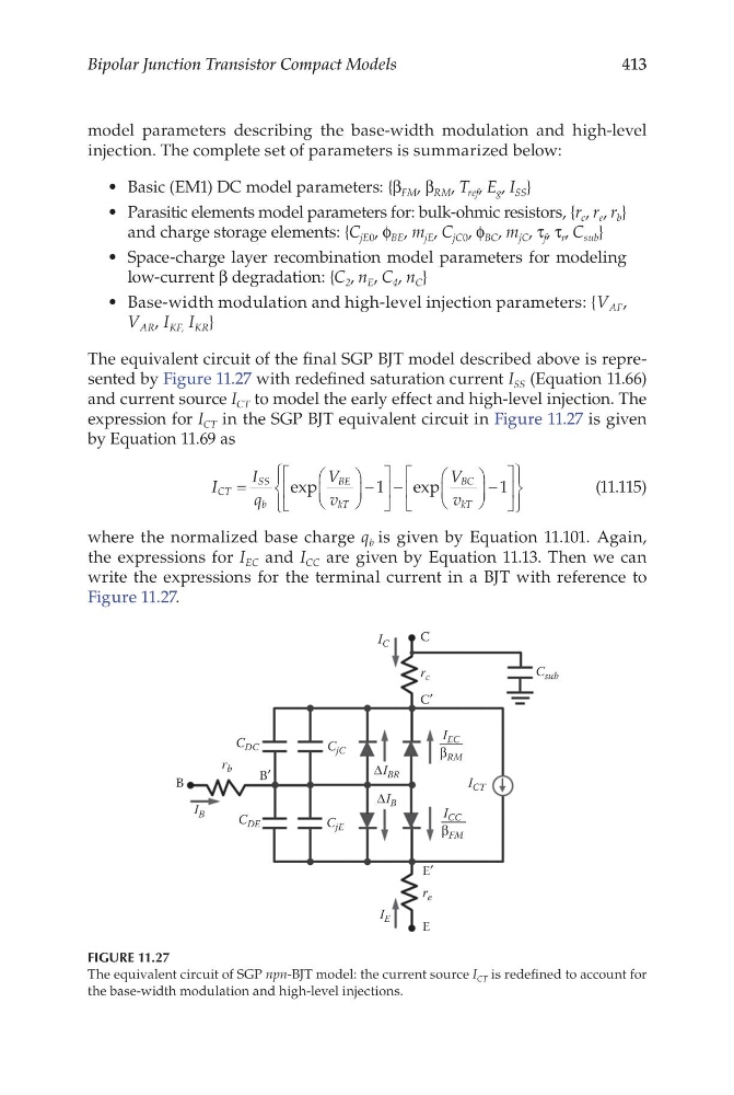
The equivalent circuit of the final SGP BJT model described above is represented by Figure 11.27 with redefined saturation current I SS (Equation 11.66)
and current source I CT to model the early effect and high-level injection. The
expression for I CT in the SGP BJT equivalent circuit in Figure 11.27 is given
by Equation 11.69 as
I
I
q
V
v
V
v
CT
SS
b
BE
kT
BC
kT
=
−
−
−
exp
e xp
1
1
(11.115)
where the normalized base charge q b is given by Equation 11.101. Again,
the expressions for I EC and I CC are given by Equation 11.13. Then we can
write the expressions for the terminal current in a BJT with reference to
Figure 11.27.
E′
C′
B′
C
E
B
r c
C sub
r b
r e
C jE
C jC
C DE
C DC
I B
I C
I E
I CT
I EC
β RM
I CC
β FM
ΔI BR
ΔI B
FIGURE 11.27
The equivalent circuit of SGP npn-BJT model: the current source I CT is redefined to account for
the base-width modulation and high-level injections.
Bipolar Junction Transistor Compact Models
model parameters describing the base-width modulation and high-level
injection. The complete set of parameters is summarized below:
• Basic (EM1) DC model parameters: {β FM , β RM , T ref , E g , I SS }
• Parasitic elements model parameters for: bulk-ohmic resistors, {r c , r e , r b }
and charge storage elements: {C jE0 , f BE , m jE , C jC0 , f BC , m jC , τ f , τ r , C sub }
• Space-charge layer recombination model parameters for modeling
low-current β degradation: {C 2 , n E , C 4 , n C }
• Base-width modulation and high-level injection parameters: {V AF ,
V AR , I KF, I KR }
The equivalent circuit of the final SGP BJT model described above is represented by Figure 11.27 with redefined saturation current I SS (Equation 11.66)
and current source I CT to model the early effect and high-level injection. The
expression for I CT in the SGP BJT equivalent circuit in Figure 11.27 is given
by Equation 11.69 as
I
I
q
V
v
V
v
CT
SS
b
BE
kT
BC
kT
=
−
−
−
exp
e xp
1
1
(11.115)
where the normalized base charge q b is given by Equation 11.101. Again,
the expressions for I EC and I CC are given by Equation 11.13. Then we can
write the expressions for the terminal current in a BJT with reference to
Figure 11.27.
E′
C′
B′
C
E
B
r c
C sub
r b
r e
C jE
C jC
C DE
C DC
I B
I C
I E
I CT
I EC
β RM
I CC
β FM
ΔI BR
ΔI B
FIGURE 11.27
The equivalent circuit of SGP npn-BJT model: the current source I CT is redefined to account for
the base-width modulation and high-level injections.