

412
Compact Models for Integrated Circuit Design
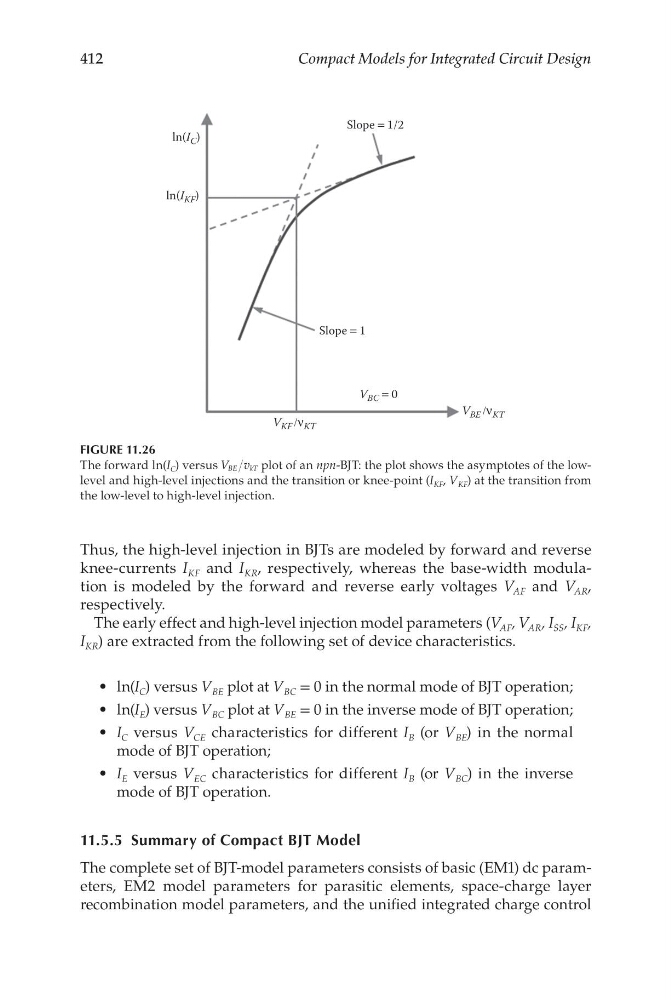
Thus, the high-level injection in BJTs are modeled by forward and reverse
knee-currents I KF and I KR , respectively, whereas the base-width modulation is modeled by the forward and reverse early voltages V AF and V AR ,
respectively.
The early effect and high-level injection model parameters (V AF , V AR , I SS , I KF ,
I KR ) are extracted from the following set of device characteristics.
• ln(I C ) versus V BE plot at V BC = 0 in the normal mode of BJT operation;
• ln(I E ) versus V BC plot at V BE = 0 in the inverse mode of BJT operation;
• I C versus V CE characteristics for different I B (or V BE ) in the normal
mode of BJT operation;
• I E versus V EC characteristics for different I B (or V BC ) in the inverse
mode of BJT operation.
11.5.5 Summary of Compact BJT Model
The complete set of BJT-model parameters consists of basic (EM1) dc parameters, EM2 model parameters for parasitic elements, space-charge layer
recombination model parameters, and the unified integrated charge control
V BC = 0
V KF /ν KT
V BE /ν KT
Slope = 1/2
Slope = 1
ln(I C )
ln(I KF )
FIGURE 11.26
The forward ln(I C ) versus V v
BE
kT plot of an npn-BJT: the plot shows the asymptotes of the lowlevel and high-level injections and the transition or knee-point (I KF , V KF ) at the transition from
the low-level to high-level injection.
Compact Models for Integrated Circuit Design
Thus, the high-level injection in BJTs are modeled by forward and reverse
knee-currents I KF and I KR , respectively, whereas the base-width modulation is modeled by the forward and reverse early voltages V AF and V AR ,
respectively.
The early effect and high-level injection model parameters (V AF , V AR , I SS , I KF ,
I KR ) are extracted from the following set of device characteristics.
• ln(I C ) versus V BE plot at V BC = 0 in the normal mode of BJT operation;
• ln(I E ) versus V BC plot at V BE = 0 in the inverse mode of BJT operation;
• I C versus V CE characteristics for different I B (or V BE ) in the normal
mode of BJT operation;
• I E versus V EC characteristics for different I B (or V BC ) in the inverse
mode of BJT operation.
11.5.5 Summary of Compact BJT Model
The complete set of BJT-model parameters consists of basic (EM1) dc parameters, EM2 model parameters for parasitic elements, space-charge layer
recombination model parameters, and the unified integrated charge control
V BC = 0
V KF /ν KT
V BE /ν KT
Slope = 1/2
Slope = 1
ln(I C )
ln(I KF )
FIGURE 11.26
The forward ln(I C ) versus V v
BE
kT plot of an npn-BJT: the plot shows the asymptotes of the lowlevel and high-level injections and the transition or knee-point (I KF , V KF ) at the transition from
the low-level to high-level injection.