

395
Bipolar Junction Transistor Compact Models
Here, I S (0) is the revised reverse saturation current of the transistor. Thus,
combining Equations 11.20 and 11.49, the forward diode current can be
modeled by
I
I
V
v
C I
V
n v
B
S
FM
BE
kT
S
BE
E kT
=
−
+
( ) exp
() exp
0
1
0
2
β
−
1
(11.50)
Similarly, we can model the minority carrier recombination in the CB-depletion
region only by another nonideal CB pn-junction by setting V BE = 0 in the inverse
mode of BJT operation with V BC > 0. Two additional parameters used to model
the components of I B are low-current inverse emission coefficient n C (~2) and
component of I S in the inverse region C 4 . Thus, ΔI B in the inverse region is
through the nonideal CB-diode is given by
∆I
C I
V
n v
BR
S
BC
C kT
=
−
4
0
1
( ) exp
(11.51)
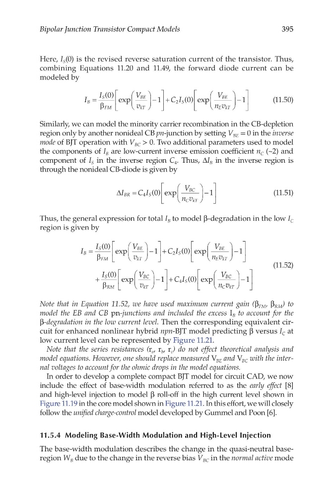
Thus, the general expression for total I B to model β-degradation in the low I C
region is given by
I
I
V
v
C I
V
n v
B
S
FM
BE
kT
S
BE
E kT
=
−
+
( ) exp
() exp
0
1
0
2
β
−
+
−
+
1
0
1
0
4
I
V
v
C I
V
n
S
RM
BC
kT
S
BC
C
( ) exp
() exp
β
v v kT
−
1
(11.52)
Note that in Equation 11.52, we have used maximum current gain (β FM , β RM ) to
model the EB and CB pn-junctions and included the excess I B to account for the
β-degradation in the low current level. Then the corresponding equivalent circuit for enhanced nonlinear hybrid npn-BJT model predicting β versus I C at
low current level can be represented by Figure 11.21.
Note that the series resistances (r e , r b , r c ) do not effect theoretical analysis and
model equations. However, one should replace measured V BE and V BC with the internal voltages to account for the ohmic drops in the model equations.
In order to develop a complete compact BJT model for circuit CAD, we now
include the effect of base-width modulation referred to as the early effect [8]
and high-level injection to model β roll-off in the high current level shown in
Figure 11.19 in the core model shown in Figure 11.21. In this effort, we will closely
follow the unified charge-control model developed by Gummel and Poon [6].
11.5.4 Modeling Base-Width Modulation and High-Level Injection
The base-width modulation describes the change in the quasi-neutral baseregion W B due to the change in the reverse bias V BC in the normal active mode
Bipolar Junction Transistor Compact Models
Here, I S (0) is the revised reverse saturation current of the transistor. Thus,
combining Equations 11.20 and 11.49, the forward diode current can be
modeled by
I
I
V
v
C I
V
n v
B
S
FM
BE
kT
S
BE
E kT
=
−
+
( ) exp
() exp
0
1
0
2
β
−
1
(11.50)
Similarly, we can model the minority carrier recombination in the CB-depletion
region only by another nonideal CB pn-junction by setting V BE = 0 in the inverse
mode of BJT operation with V BC > 0. Two additional parameters used to model
the components of I B are low-current inverse emission coefficient n C (~2) and
component of I S in the inverse region C 4 . Thus, ΔI B in the inverse region is
through the nonideal CB-diode is given by
∆I
C I
V
n v
BR
S
BC
C kT
=
−
4
0
1
( ) exp
(11.51)
Thus, the general expression for total I B to model β-degradation in the low I C
region is given by
I
I
V
v
C I
V
n v
B
S
FM
BE
kT
S
BE
E kT
=
−
+
( ) exp
() exp
0
1
0
2
β
−
+
−
+
1
0
1
0
4
I
V
v
C I
V
n
S
RM
BC
kT
S
BC
C
( ) exp
() exp
β
v v kT
−
1
(11.52)
Note that in Equation 11.52, we have used maximum current gain (β FM , β RM ) to
model the EB and CB pn-junctions and included the excess I B to account for the
β-degradation in the low current level. Then the corresponding equivalent circuit for enhanced nonlinear hybrid npn-BJT model predicting β versus I C at
low current level can be represented by Figure 11.21.
Note that the series resistances (r e , r b , r c ) do not effect theoretical analysis and
model equations. However, one should replace measured V BE and V BC with the internal voltages to account for the ohmic drops in the model equations.
In order to develop a complete compact BJT model for circuit CAD, we now
include the effect of base-width modulation referred to as the early effect [8]
and high-level injection to model β roll-off in the high current level shown in
Figure 11.19 in the core model shown in Figure 11.21. In this effort, we will closely
follow the unified charge-control model developed by Gummel and Poon [6].
11.5.4 Modeling Base-Width Modulation and High-Level Injection
The base-width modulation describes the change in the quasi-neutral baseregion W B due to the change in the reverse bias V BC in the normal active mode