

382
Compact Models for Integrated Circuit Design
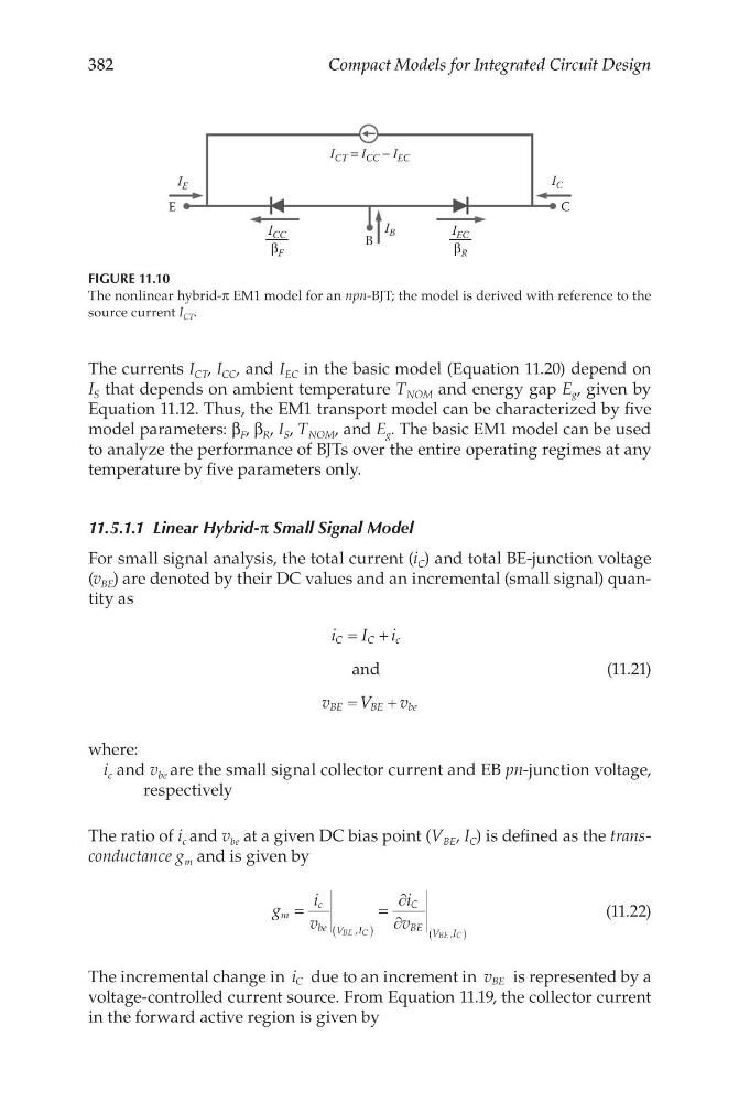
The currents I CT , I CC , and I EC in the basic model (Equation 11.20) depend on
I S that depends on ambient temperature T NOM and energy gap E g , given by
Equation 11.12. Thus, the EM1 transport model can be characterized by five
model parameters: β F , β R , I S , T NOM , and E g . The basic EM1 model can be used
to analyze the performance of BJTs over the entire operating regimes at any
temperature by five parameters only.
11.5.1.1 Linear Hybrid-π Small Signal Model
For small signal analysis, the total current (i C ) and total BE-junction voltage
(v BE ) are denoted by their DC values and an incremental (small signal) quantity as
i
I i
v
V
v
C
C
c
BE
BE
be
= +
=
+
and
(11.21)
where:
i c and v be are the small signal collector current and EB pn-junction voltage,
respectively
The ratio of i c and v be at a given DC bias point (V BE , I C ) is defined as the transconductance g m and is given by
g
i
v
i
v
m
c
be V I
C
BE V I
BE C
BE C
=
=
∂
∂
(
)
(
)
,
,
(11.22)
The incremental change in i C due to an increment in v BE is represented by a
voltage-controlled current source. From Equation 11.19, the collector current
in the forward active region is given by
E
I E
I EC
B
I B
C
I C
I CT = I CC − I EC
I CC
β R
β F
FIGURE 11.10
The nonlinear hybrid-π EM1 model for an npn-BJT; the model is derived with reference to the
source current I CT .
Compact Models for Integrated Circuit Design
The currents I CT , I CC , and I EC in the basic model (Equation 11.20) depend on
I S that depends on ambient temperature T NOM and energy gap E g , given by
Equation 11.12. Thus, the EM1 transport model can be characterized by five
model parameters: β F , β R , I S , T NOM , and E g . The basic EM1 model can be used
to analyze the performance of BJTs over the entire operating regimes at any
temperature by five parameters only.
11.5.1.1 Linear Hybrid-π Small Signal Model
For small signal analysis, the total current (i C ) and total BE-junction voltage
(v BE ) are denoted by their DC values and an incremental (small signal) quantity as
i
I i
v
V
v
C
C
c
BE
BE
be
= +
=
+
and
(11.21)
where:
i c and v be are the small signal collector current and EB pn-junction voltage,
respectively
The ratio of i c and v be at a given DC bias point (V BE , I C ) is defined as the transconductance g m and is given by
g
i
v
i
v
m
c
be V I
C
BE V I
BE C
BE C
=
=
∂
∂
(
)
(
)
,
,
(11.22)
The incremental change in i C due to an increment in v BE is represented by a
voltage-controlled current source. From Equation 11.19, the collector current
in the forward active region is given by
E
I E
I EC
B
I B
C
I C
I CT = I CC − I EC
I CC
β R
β F
FIGURE 11.10
The nonlinear hybrid-π EM1 model for an npn-BJT; the model is derived with reference to the
source current I CT .