

375
Bipolar Junction Transistor Compact Models
11.4 Mode of Operations of BJTs
In order to develop compact BJT models for circuit CAD, let us define the
operation regions of BJT devices. Depending on the biasing conditions, we
can define four different modes of BJT operations as shown in Figure 11.5 for
an npn-BJT device.
1. Forward active or normal mode: EB-junction is forward biased; and
CB-junction is reverse biased. In this case, the collector current
I C = β F I B , where β F is the forward current gain;
(a)
(b)
Electrons flow from
emitter to collector
Recombining electrons
Holes
into emitter
E
E
B
B
C
C
X dEB
I E
I B
I E
I C
I C
I B
X dCB
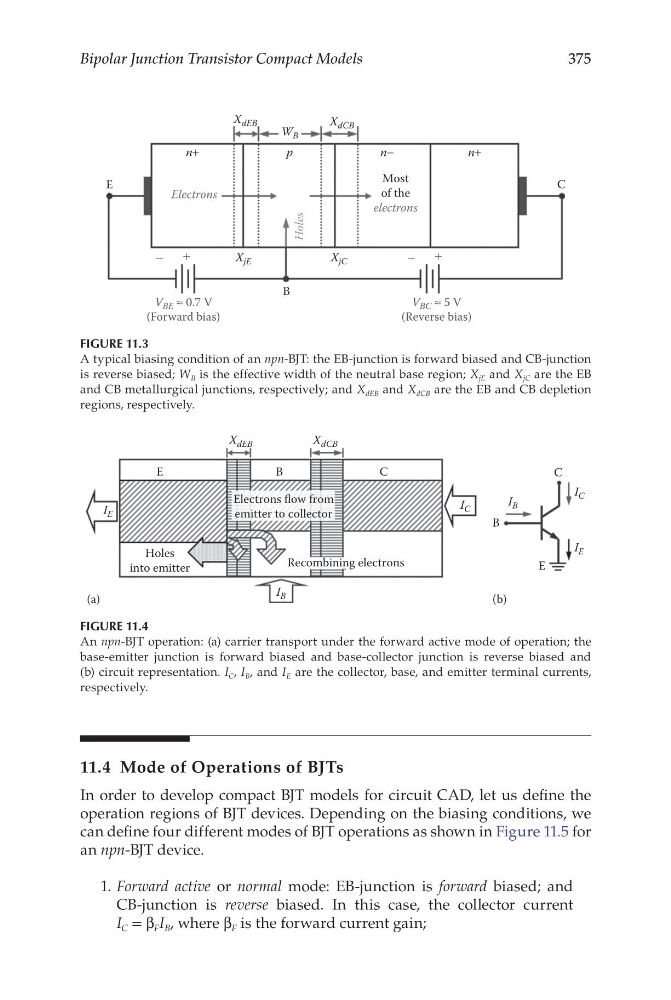
FIGURE 11.4
An npn-BJT operation: (a) carrier transport under the forward active mode of operation; the
base-emitter junction is forward biased and base-collector junction is reverse biased and
(b) circuit representation. I C , I B , and I E are the collector, base, and emitter terminal currents,
respectively.
Most
of the
electrons
Electrons
Holes
V BE ≈ 0.7 V
(Forward bias)
V BC ≈ 5 V
(Reverse bias)
X jE
X dEB
X dCB
W B
B
C
E
X jC
n+
n+
n−
p
+
−
+
−
FIGURE 11.3
A typical biasing condition of an npn-BJT: the EB-junction is forward biased and CB-junction
is reverse biased; W B is the effective width of the neutral base region; X jE and X jC are the EB
and CB metallurgical junctions, respectively; and X dEB and X dCB are the EB and CB depletion
regions, respectively.
Bipolar Junction Transistor Compact Models
11.4 Mode of Operations of BJTs
In order to develop compact BJT models for circuit CAD, let us define the
operation regions of BJT devices. Depending on the biasing conditions, we
can define four different modes of BJT operations as shown in Figure 11.5 for
an npn-BJT device.
1. Forward active or normal mode: EB-junction is forward biased; and
CB-junction is reverse biased. In this case, the collector current
I C = β F I B , where β F is the forward current gain;
(a)
(b)
Electrons flow from
emitter to collector
Recombining electrons
Holes
into emitter
E
E
B
B
C
C
X dEB
I E
I B
I E
I C
I C
I B
X dCB
FIGURE 11.4
An npn-BJT operation: (a) carrier transport under the forward active mode of operation; the
base-emitter junction is forward biased and base-collector junction is reverse biased and
(b) circuit representation. I C , I B , and I E are the collector, base, and emitter terminal currents,
respectively.
Most
of the
electrons
Electrons
Holes
V BE ≈ 0.7 V
(Forward bias)
V BC ≈ 5 V
(Reverse bias)
X jE
X dEB
X dCB
W B
B
C
E
X jC
n+
n+
n−
p
+
−
+
−
FIGURE 11.3
A typical biasing condition of an npn-BJT: the EB-junction is forward biased and CB-junction
is reverse biased; W B is the effective width of the neutral base region; X jE and X jC are the EB
and CB metallurgical junctions, respectively; and X dEB and X dCB are the EB and CB depletion
regions, respectively.