

376
Compact Models for Integrated Circuit Design
2. Reverse active mode: EB-junction is reverse biased and CB-junction is
forward biased. In this case, the reverse current at emitter terminal
I E = β R I B , where β R is the reverse current gain ≈ 1;
3. Saturation: both EB- and CB-junctions are forward biased;
4. Cutoff: both EB- and CB-junctions are reverse biased.
Similarly, we can define the different regions of a pnp-BJT operation by
appropriately changing the sign of V BE and V CE .
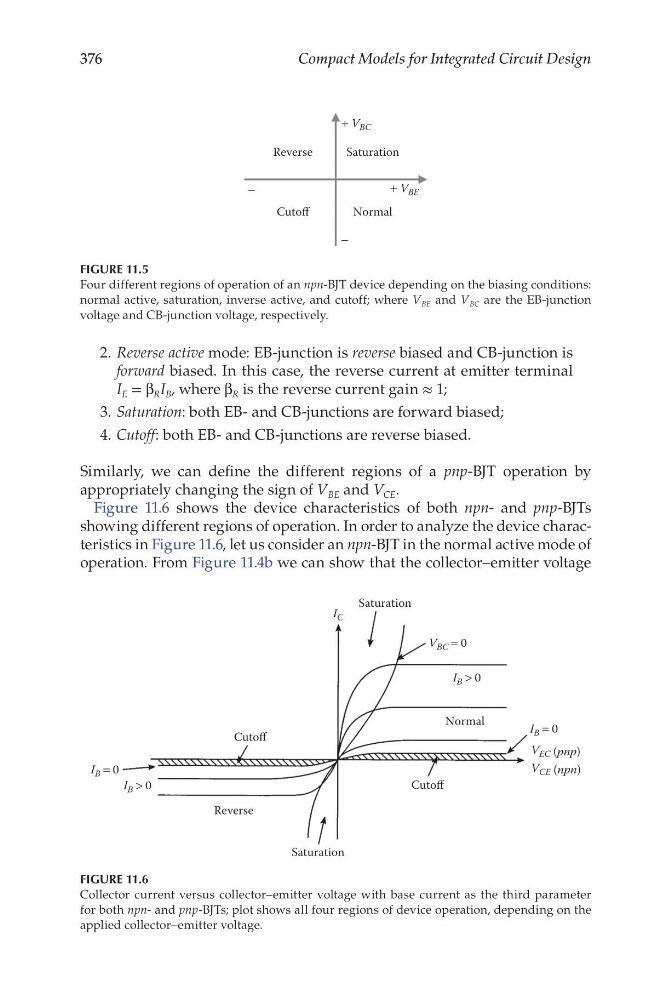
Figure 11.6 shows the device characteristics of both npn- and pnp-BJTs
showing different regions of operation. In order to analyze the device characteristics in Figure 11.6, let us consider an npn-BJT in the normal active mode of
operation. From Figure 11.4b we can show that the collector–emitter voltage
Reverse
Cutoff
Cutoff
Saturation
Saturation
Normal
V EC (pnp)
V CE (npn)
V BC = 0
I B > 0
I B = 0
I B = 0
I B > 0
I C
FIGURE 11.6
Collector current versus collector–emitter voltage with base current as the third parameter
for both npn- and pnp-BJTs; plot shows all four regions of device operation, depending on the
applied collector–emitter voltage.
Reverse
Cutoff
Saturation
Normal
+ V BC
+ V BE
−
−
FIGURE 11.5
Four different regions of operation of an npn-BJT device depending on the biasing conditions:
normal active, saturation, inverse active, and cutoff; where V BE and V BC are the EB-junction
voltage and CB-junction voltage, respectively.
Compact Models for Integrated Circuit Design
2. Reverse active mode: EB-junction is reverse biased and CB-junction is
forward biased. In this case, the reverse current at emitter terminal
I E = β R I B , where β R is the reverse current gain ≈ 1;
3. Saturation: both EB- and CB-junctions are forward biased;
4. Cutoff: both EB- and CB-junctions are reverse biased.
Similarly, we can define the different regions of a pnp-BJT operation by
appropriately changing the sign of V BE and V CE .
Figure 11.6 shows the device characteristics of both npn- and pnp-BJTs
showing different regions of operation. In order to analyze the device characteristics in Figure 11.6, let us consider an npn-BJT in the normal active mode of
operation. From Figure 11.4b we can show that the collector–emitter voltage
Reverse
Cutoff
Cutoff
Saturation
Saturation
Normal
V EC (pnp)
V CE (npn)
V BC = 0
I B > 0
I B = 0
I B = 0
I B > 0
I C
FIGURE 11.6
Collector current versus collector–emitter voltage with base current as the third parameter
for both npn- and pnp-BJTs; plot shows all four regions of device operation, depending on the
applied collector–emitter voltage.
Reverse
Cutoff
Saturation
Normal
+ V BC
+ V BE
−
−
FIGURE 11.5
Four different regions of operation of an npn-BJT device depending on the biasing conditions:
normal active, saturation, inverse active, and cutoff; where V BE and V BC are the EB-junction
voltage and CB-junction voltage, respectively.