

350
Compact Models for Integrated Circuit Design
energy and the effective mass m* must then be changed to reduce effective
mass m r * in the tunneling direction for accurate prediction of tunneling current
in the indirect semiconductors.
In Equation 10.2, λ describes the spatial extent of the transition region at
the source-channel interface as shown in Figure 10.3 and depends on the
biasing condition and device dimension. λ is also known as the screening
length, natural length, and Debye length that physically refers to the spatial
extent of the electric field or the length over which an electric charge has an
influence before being screened out by the opposite charges around it [52].
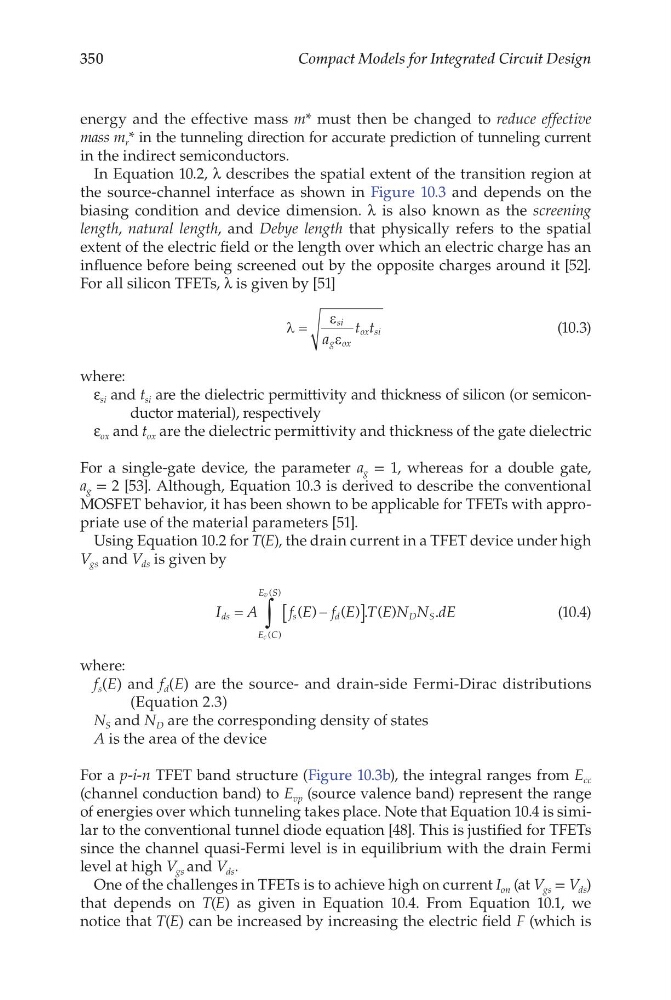
For all silicon TFETs, λ is given by [51]
λ
ε
ε
=
si
g ox
ox si
a
t t
(10.3)
where:
ε si and t si are the dielectric permittivity and thickness of silicon (or semiconductor material), respectively
ε ox and t ox are the dielectric permittivity and thickness of the gate dielectric
For a single-gate device, the parameter a g = 1, whereas for a double gate,
a g = 2 [53]. Although, Equation 10.3 is derived to describe the conventional
MOSFET behavior, it has been shown to be applicable for TFETs with appropriate use of the material parameters [51].
Using Equation 10.2 for T(E), the drain current in a TFET device under high
V gs and V ds is given by
I
A
f E f E T E N N dE
ds
s
d
E C
E S
D S
c
v
=
−
[
]
∫
( )
( ) . ( )
.
( )
( )
(10.4)
where:
f s (E) and f d (E) are the source- and drain-side Fermi-Dirac distributions
(Equation 2.3)
N S and N D are the corresponding density of states
A is the area of the device
For a p-i-n TFET band structure (Figure 10.3b), the integral ranges from E cc
(channel conduction band) to E vp (source valence band) represent the range
of energies over which tunneling takes place. Note that Equation 10.4 is similar to the conventional tunnel diode equation [48]. This is justified for TFETs
since the channel quasi-Fermi level is in equilibrium with the drain Fermi
level at high V gs and V ds .
One of the challenges in TFETs is to achieve high on current I on (at V gs = V ds )
that depends on T(E) as given in Equation 10.4. From Equation 10.1, we
notice that T(E) can be increased by increasing the electric field F (which is
Compact Models for Integrated Circuit Design
energy and the effective mass m* must then be changed to reduce effective
mass m r * in the tunneling direction for accurate prediction of tunneling current
in the indirect semiconductors.
In Equation 10.2, λ describes the spatial extent of the transition region at
the source-channel interface as shown in Figure 10.3 and depends on the
biasing condition and device dimension. λ is also known as the screening
length, natural length, and Debye length that physically refers to the spatial
extent of the electric field or the length over which an electric charge has an
influence before being screened out by the opposite charges around it [52].
For all silicon TFETs, λ is given by [51]
λ
ε
ε
=
si
g ox
ox si
a
t t
(10.3)
where:
ε si and t si are the dielectric permittivity and thickness of silicon (or semiconductor material), respectively
ε ox and t ox are the dielectric permittivity and thickness of the gate dielectric
For a single-gate device, the parameter a g = 1, whereas for a double gate,
a g = 2 [53]. Although, Equation 10.3 is derived to describe the conventional
MOSFET behavior, it has been shown to be applicable for TFETs with appropriate use of the material parameters [51].
Using Equation 10.2 for T(E), the drain current in a TFET device under high
V gs and V ds is given by
I
A
f E f E T E N N dE
ds
s
d
E C
E S
D S
c
v
=
−
[
]
∫
( )
( ) . ( )
.
( )
( )
(10.4)
where:
f s (E) and f d (E) are the source- and drain-side Fermi-Dirac distributions
(Equation 2.3)
N S and N D are the corresponding density of states
A is the area of the device
For a p-i-n TFET band structure (Figure 10.3b), the integral ranges from E cc
(channel conduction band) to E vp (source valence band) represent the range
of energies over which tunneling takes place. Note that Equation 10.4 is similar to the conventional tunnel diode equation [48]. This is justified for TFETs
since the channel quasi-Fermi level is in equilibrium with the drain Fermi
level at high V gs and V ds .
One of the challenges in TFETs is to achieve high on current I on (at V gs = V ds )
that depends on T(E) as given in Equation 10.4. From Equation 10.1, we
notice that T(E) can be increased by increasing the electric field F (which is