

339
Compact Models for Ultrathin Body FETs
I
dQ
dt
C
dV
dt
x
x
xy
y
y
=
= ∑
(9.74)
where x, y = d, fg, bg, s; each transcapacitance is defined as
C
Q
V
xy
x
y
=
∂
∂
(9.75)
The charge associated with the front gate fg can be calculated as
Q
W C V
y dy
fg
ox
L
fg
s
=
−
−
∫
1
0
1
1
∆Φ φ ( )
(9.76)
where:
ΔΦ 1 is the work function of the front gate with reference to that of n+
source
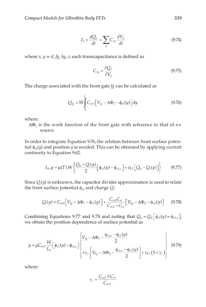
In order to integrate Equation 9.76, the relation between front surface potential f s1 (y) and position y is needed. This can be obtained by applying current
continuity to Equation 9.62.
I y
T W
Q Q y
y
v Q Q y
ds
is
i
s
ss
k T
i s
i
.
( ).
( )
( )
( )
,
=
+
−
+
−
µ
φ
φ
2
1
1
(9.77)
Since Q i (y) is unknown, the capacitor divider approximation is used to relate
the front surface potential f s1 and charge Q i :
Q y C V
y
C C
C
C
V
y
i
o x
f g
s
ox
si
ox
si
bg
s
( )
( )
( )
=
−
−
+
+
−
−
1
1
1
2
2
2
2
∆Φ
∆Φ
φ
φ
(9.78)
Combining Equations 9.77 and 9.78 and noting that Q Q
y
is
is
s
ss
=
=
φ
φ
1
1
( )
, ,
we obtain the position dependence of surface potential as
y
C
W
I
y
V
y
V
ox
ds
s
ss
fg
s s
s
c
b g
=
−
−
−
−
+
−
µ
φ
φ
φ
φ
γ
1
1
1
1
1
1
2
( )
( )
.
,
,
∆Φ
∆Φ 2 2
1
1
2
1
−
−
+
+
(
)
φ
φ
γ
s s
s
kT
c
y
v
,
( )
(9.79)
where:
γ c
ox
si
ox
C
C
C
=
2
1
| |
Compact Models for Ultrathin Body FETs
I
dQ
dt
C
dV
dt
x
x
xy
y
y
=
= ∑
(9.74)
where x, y = d, fg, bg, s; each transcapacitance is defined as
C
Q
V
xy
x
y
=
∂
∂
(9.75)
The charge associated with the front gate fg can be calculated as
Q
W C V
y dy
fg
ox
L
fg
s
=
−
−
∫
1
0
1
1
∆Φ φ ( )
(9.76)
where:
ΔΦ 1 is the work function of the front gate with reference to that of n+
source
In order to integrate Equation 9.76, the relation between front surface potential f s1 (y) and position y is needed. This can be obtained by applying current
continuity to Equation 9.62.
I y
T W
Q Q y
y
v Q Q y
ds
is
i
s
ss
k T
i s
i
.
( ).
( )
( )
( )
,
=
+
−
+
−
µ
φ
φ
2
1
1
(9.77)
Since Q i (y) is unknown, the capacitor divider approximation is used to relate
the front surface potential f s1 and charge Q i :
Q y C V
y
C C
C
C
V
y
i
o x
f g
s
ox
si
ox
si
bg
s
( )
( )
( )
=
−
−
+
+
−
−
1
1
1
2
2
2
2
∆Φ
∆Φ
φ
φ
(9.78)
Combining Equations 9.77 and 9.78 and noting that Q Q
y
is
is
s
ss
=
=
φ
φ
1
1
( )
, ,
we obtain the position dependence of surface potential as
y
C
W
I
y
V
y
V
ox
ds
s
ss
fg
s s
s
c
b g
=
−
−
−
−
+
−
µ
φ
φ
φ
φ
γ
1
1
1
1
1
1
2
( )
( )
.
,
,
∆Φ
∆Φ 2 2
1
1
2
1
−
−
+
+
(
)
φ
φ
γ
s s
s
kT
c
y
v
,
( )
(9.79)
where:
γ c
ox
si
ox
C
C
C
=
2
1
| |