

337
Compact Models for Ultrathin Body FETs
I L I y
y L
d
d
( ) ( )
=
≤ ≤
, where 0
(9.66)
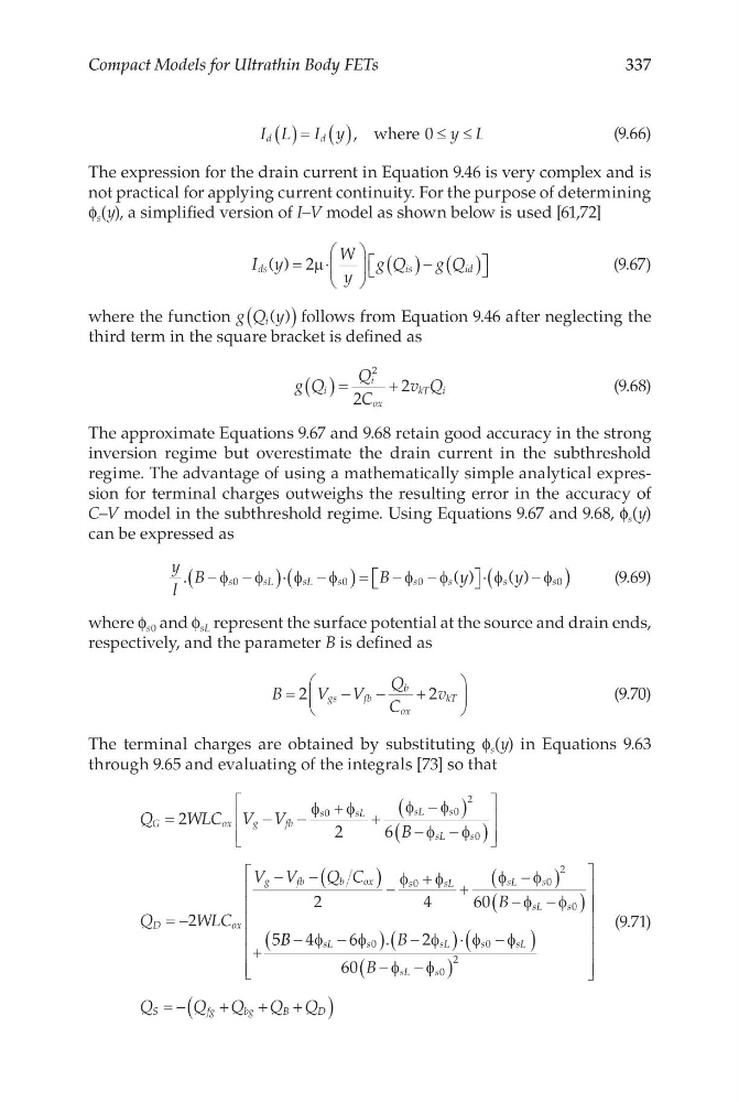
The expression for the drain current in Equation 9.46 is very complex and is
not practical for applying current continuity. For the purpose of determining
f s (y), a simplified version of I–V model as shown below is used [61,72]
I y
W
y
g Q
g Q
ds
is
id
( ) = ⋅
( )− ( )
2µ
(9.67)
where the function g Q y
i ( )
(
) follows from Equation 9.46 after neglecting the
third term in the square bracket is defined as
g Q
Q
C
v Q
i
i
ox
kT i
( )=
+
2
2
2
(9.68)
The approximate Equations 9.67 and 9.68 retain good accuracy in the strong
inversion regime but overestimate the drain current in the subthreshold
regime. The advantage of using a mathematically simple analytical expression for terminal charges outweighs the resulting error in the accuracy of
C–V model in the subthreshold regime. Using Equations 9.67 and 9.68, f s (y)
can be expressed as
y
l
B
B
y
y
s
s L
s L
s
s
s
s
s
.
( )
( )
−
−
(
) ⋅ −
(
)= − −
⋅
−
(
)
φ
φ
φ
φ
φ
φ
φ
φ
0
0
0
0
(9.69)
where f s0 and f sL represent the surface potential at the source and drain ends,
respectively, and the parameter B is defined as
B
V V
Q
C
v
gs
fb
b
ox
kT
=
−
−
+
2
2
(9.70)
The terminal charges are obtained by substituting f s (y) in Equations 9.63
through 9.65 and evaluating of the integrals [73] so that
Q
WLC V V
B
Q
G
o x
g
fb
s
s L
sL
s
sL
s
D
=
−
−
+
+
−
(
)
−
−
(
)
=
2
2
6
2
φ
φ
φ
φ
φ
φ
0
0
0
− −
−
−(
) −
+
+
−
(
)
−
−
(
)
+
2
2
4
60
5
2
WLC
V V
Q C
B
ox
g
f b
b
ox
s
s L
sL
s
sL
s
φ
φ
φ
φ
φ
φ
0
0
0
B B
B
B
sL
s
s L
s
sL
sL
s
−
−
(
) −
(
)⋅ −
(
)
−
−
(
)
4
6
2
60
2
φ
φ
φ
φ
φ
φ
φ
0
0
0
.
= −
+
+
+
(
)
Q
Q Q
Q Q
S
f g
b g
B
D
(9.71)
Compact Models for Ultrathin Body FETs
I L I y
y L
d
d
( ) ( )
=
≤ ≤
, where 0
(9.66)
The expression for the drain current in Equation 9.46 is very complex and is
not practical for applying current continuity. For the purpose of determining
f s (y), a simplified version of I–V model as shown below is used [61,72]
I y
W
y
g Q
g Q
ds
is
id
( ) = ⋅
( )− ( )
2µ
(9.67)
where the function g Q y
i ( )
(
) follows from Equation 9.46 after neglecting the
third term in the square bracket is defined as
g Q
Q
C
v Q
i
i
ox
kT i
( )=
+
2
2
2
(9.68)
The approximate Equations 9.67 and 9.68 retain good accuracy in the strong
inversion regime but overestimate the drain current in the subthreshold
regime. The advantage of using a mathematically simple analytical expression for terminal charges outweighs the resulting error in the accuracy of
C–V model in the subthreshold regime. Using Equations 9.67 and 9.68, f s (y)
can be expressed as
y
l
B
B
y
y
s
s L
s L
s
s
s
s
s
.
( )
( )
−
−
(
) ⋅ −
(
)= − −
⋅
−
(
)
φ
φ
φ
φ
φ
φ
φ
φ
0
0
0
0
(9.69)
where f s0 and f sL represent the surface potential at the source and drain ends,
respectively, and the parameter B is defined as
B
V V
Q
C
v
gs
fb
b
ox
kT
=
−
−
+
2
2
(9.70)
The terminal charges are obtained by substituting f s (y) in Equations 9.63
through 9.65 and evaluating of the integrals [73] so that
Q
WLC V V
B
Q
G
o x
g
fb
s
s L
sL
s
sL
s
D
=
−
−
+
+
−
(
)
−
−
(
)
=
2
2
6
2
φ
φ
φ
φ
φ
φ
0
0
0
− −
−
−(
) −
+
+
−
(
)
−
−
(
)
+
2
2
4
60
5
2
WLC
V V
Q C
B
ox
g
f b
b
ox
s
s L
sL
s
sL
s
φ
φ
φ
φ
φ
φ
0
0
0
B B
B
B
sL
s
s L
s
sL
sL
s
−
−
(
) −
(
)⋅ −
(
)
−
−
(
)
4
6
2
60
2
φ
φ
φ
φ
φ
φ
φ
0
0
0
.
= −
+
+
+
(
)
Q
Q Q
Q Q
S
f g
b g
B
D
(9.71)