

295
Modeling Process Variability in Scaled MOSFETs
Then, the UL is set by taking the appropriate maximum or minimum offset of model parameters to maximize the value of I ds . Thus, the UL of ION,
defined at V ds = V dsat for nMOSFETs is given by:
IONN UL
W dW
L dL
T dT
V
V dV
eff
ox
ox
ox
gs
th
t
( )
(
)
≅
+
−
−
−
−
µ
ε
2
h h
(
)
2
(8.13)
In Equation 8.13, W is increased by dW, L is reduced by dL, T ox is reduced
by dT ox , and V th is reduced by dV th to achieve the UL of ION specification.
Similarly, the LL for ION is set by
IONN LL
W dW
L dL
T
dT
V
V dV
eff
ox
ox
ox
gs
th
t
( )
(
)
≅
−
+
+
−
+
µ
ε
2
h h
(
)
2
(8.14)
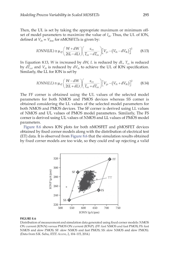
The FF corner is obtained using the UL values of the selected model
parameters for both NMOS and PMOS devices whereas SS corner is
obtained considering the LL values of the selected model parameters for
both NMOS and PMOS devices. The SF corner is derived using LL values
of NMOS and UL values of PMOS model parameters. Similarly, The FS
corner is derived using UL values of NMOS and LL values of PMOS model
parameters.
Figure 8.6 shows ION plots for both nMOSFET and pMOSFET devices
obtained by fixed corner models along with the distribution of electrical test
(ET) data. It is observed from Figure 8.6 that the simulation results obtained
by fixed corner models are too wide, so they could end up rejecting a valid
500
220
SS
FS
SF
FF
TT
240
260
280
300
320
550
600
IONN (μA/μm)
IONP (μA/μm)
650
700
750
FIGURE 8.6
Distribution of measurement and simulation data generated using fixed corner models: NMOS
ON current (IONN) versus PMOS ON current (IONP). (FF: fast NMOS and fast PMOS; FS: fast
NMOS and slow PMOS; SF: slow NMOS and fast PMOS; SS: slow NMOS and slow PMOS).
(Data from S.K. Saha, IEEE Access, 2, 104–115, 2014.)
Modeling Process Variability in Scaled MOSFETs
Then, the UL is set by taking the appropriate maximum or minimum offset of model parameters to maximize the value of I ds . Thus, the UL of ION,
defined at V ds = V dsat for nMOSFETs is given by:
IONN UL
W dW
L dL
T dT
V
V dV
eff
ox
ox
ox
gs
th
t
( )
(
)
≅
+
−
−
−
−
µ
ε
2
h h
(
)
2
(8.13)
In Equation 8.13, W is increased by dW, L is reduced by dL, T ox is reduced
by dT ox , and V th is reduced by dV th to achieve the UL of ION specification.
Similarly, the LL for ION is set by
IONN LL
W dW
L dL
T
dT
V
V dV
eff
ox
ox
ox
gs
th
t
( )
(
)
≅
−
+
+
−
+
µ
ε
2
h h
(
)
2
(8.14)
The FF corner is obtained using the UL values of the selected model
parameters for both NMOS and PMOS devices whereas SS corner is
obtained considering the LL values of the selected model parameters for
both NMOS and PMOS devices. The SF corner is derived using LL values
of NMOS and UL values of PMOS model parameters. Similarly, The FS
corner is derived using UL values of NMOS and LL values of PMOS model
parameters.
Figure 8.6 shows ION plots for both nMOSFET and pMOSFET devices
obtained by fixed corner models along with the distribution of electrical test
(ET) data. It is observed from Figure 8.6 that the simulation results obtained
by fixed corner models are too wide, so they could end up rejecting a valid
500
220
SS
FS
SF
FF
TT
240
260
280
300
320
550
600
IONN (μA/μm)
IONP (μA/μm)
650
700
750
FIGURE 8.6
Distribution of measurement and simulation data generated using fixed corner models: NMOS
ON current (IONN) versus PMOS ON current (IONP). (FF: fast NMOS and fast PMOS; FS: fast
NMOS and slow PMOS; SF: slow NMOS and fast PMOS; SS: slow NMOS and slow PMOS).
(Data from S.K. Saha, IEEE Access, 2, 104–115, 2014.)