

272
Compact Models for Integrated Circuit Design
In the subthreshold region, it is reasonable to assume that N << N*
and N* t = A + BN + CN 2 ≅ A. Thus, the flicker noise power in the
subthreshold region can be simplified to
Si f
Aqv I
f W L N
kT ds
eff eff
( )
*
= ⋅ ⋅
2
2
γ
(7.38)
However, the flicker noise model of p-channel MOSFETs is not clear,
especially in the weak inversion region [32].
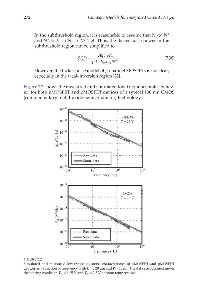
Figure 7.2 shows the measured and simulated low-frequency noise behavior for both nMOSFET and pMOSFET devices of a typical 130 nm CMOS
(complementary metal-oxide-semiconductor) technology.
10
0
10
−24
10
−22
10
−20
10
−18
S
id (A 2
/Hz)
10
−16
10
−14
NMOS
T = 25°C
10
2
10
4
Frequency (Hz)
Raw data
Simu. data
10 6
10
0
10
−24
10
−22
10
−20
10
−18
S
id (A
2
/Hz)
10
−16
10
−14
PMOS
T = 25°C
10
2
10
4
Frequency (Hz)
Raw data
Simu. data
10
6
FIGURE 7.2
Simulated and measured low-frequency noise characteristics of nMOSFET and pMOSFET
devices as a function of frequency with L = 0.28 μm and W= 10 μm; the data are obtained under
the biasing condition V gs = 1.25 V and V ds = 2.5 V at room temperature.
Compact Models for Integrated Circuit Design
In the subthreshold region, it is reasonable to assume that N << N*
and N* t = A + BN + CN 2 ≅ A. Thus, the flicker noise power in the
subthreshold region can be simplified to
Si f
Aqv I
f W L N
kT ds
eff eff
( )
*
= ⋅ ⋅
2
2
γ
(7.38)
However, the flicker noise model of p-channel MOSFETs is not clear,
especially in the weak inversion region [32].
Figure 7.2 shows the measured and simulated low-frequency noise behavior for both nMOSFET and pMOSFET devices of a typical 130 nm CMOS
(complementary metal-oxide-semiconductor) technology.
10
0
10
−24
10
−22
10
−20
10
−18
S
id (A 2
/Hz)
10
−16
10
−14
NMOS
T = 25°C
10
2
10
4
Frequency (Hz)
Raw data
Simu. data
10 6
10
0
10
−24
10
−22
10
−20
10
−18
S
id (A
2
/Hz)
10
−16
10
−14
PMOS
T = 25°C
10
2
10
4
Frequency (Hz)
Raw data
Simu. data
10
6
FIGURE 7.2
Simulated and measured low-frequency noise characteristics of nMOSFET and pMOSFET
devices as a function of frequency with L = 0.28 μm and W= 10 μm; the data are obtained under
the biasing condition V gs = 1.25 V and V ds = 2.5 V at room temperature.