

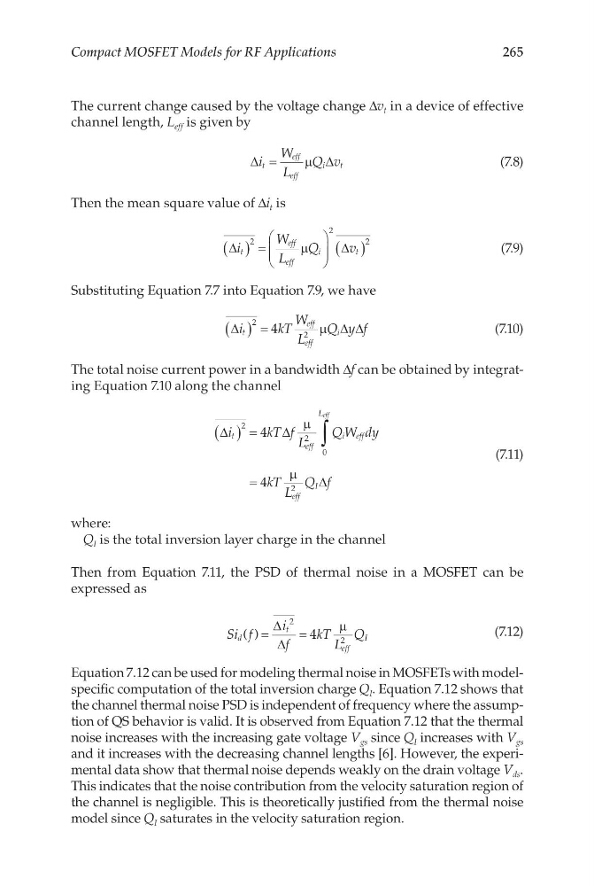
265
Compact MOSFET Models for RF Applications
The current change caused by the voltage change Δv t in a device of effective
channel length, L eff is given by
∆
∆
i
W
L
Q v
t
eff
eff
i
t
=
µ
(7.8)
Then the mean square value of Δi t is
∆
∆
i
W
L
Q
v
t
eff
eff
i
t
( ) =
( )
2
2
2
µ
(7.9)
Substituting Equation 7.7 into Equation 7.9, we have
∆
∆∆
i
kT
W
L
Q y f
t
eff
eff
i
( ) =
2
4
2
µ
(7.10)
The total noise current power in a bandwidth Δf can be obtained by integrating Equation 7.10 along the channel
∆
∆
∆
i
kT f L
QW dy
kT L
Q f
t
eff
i eff
L
eff
I
eff
( ) =
=
∫
2
2
0
2
4
4
µ
µ
(7.11)
where:
Q I is the total inversion layer charge in the channel
Then from Equation 7.11, the PSD of thermal noise in a MOSFET can be
expressed as
Si f
i
f
kT L
Q
d
t
eff
I
( ) =
=
∆
∆
2
4
µ
2
(7.12)
Equation 7.12 can be used for modeling thermal noise in MOSFETs with modelspecific computation of the total inversion charge Q I . Equation 7.12 shows that
the channel thermal noise PSD is independent of frequency where the assumption of QS behavior is valid. It is observed from Equation 7.12 that the thermal
noise increases with the increasing gate voltage V gs since Q I increases with V gs
and it increases with the decreasing channel lengths [6]. However, the experimental data show that thermal noise depends weakly on the drain voltage V ds .
This indicates that the noise contribution from the velocity saturation region of
the channel is negligible. This is theoretically justified from the thermal noise
model since Q I saturates in the velocity saturation region.
Compact MOSFET Models for RF Applications
The current change caused by the voltage change Δv t in a device of effective
channel length, L eff is given by
∆
∆
i
W
L
Q v
t
eff
eff
i
t
=
µ
(7.8)
Then the mean square value of Δi t is
∆
∆
i
W
L
Q
v
t
eff
eff
i
t
( ) =
( )
2
2
2
µ
(7.9)
Substituting Equation 7.7 into Equation 7.9, we have
∆
∆∆
i
kT
W
L
Q y f
t
eff
eff
i
( ) =
2
4
2
µ
(7.10)
The total noise current power in a bandwidth Δf can be obtained by integrating Equation 7.10 along the channel
∆
∆
∆
i
kT f L
QW dy
kT L
Q f
t
eff
i eff
L
eff
I
eff
( ) =
=
∫
2
2
0
2
4
4
µ
µ
(7.11)
where:
Q I is the total inversion layer charge in the channel
Then from Equation 7.11, the PSD of thermal noise in a MOSFET can be
expressed as
Si f
i
f
kT L
Q
d
t
eff
I
( ) =
=
∆
∆
2
4
µ
2
(7.12)
Equation 7.12 can be used for modeling thermal noise in MOSFETs with modelspecific computation of the total inversion charge Q I . Equation 7.12 shows that
the channel thermal noise PSD is independent of frequency where the assumption of QS behavior is valid. It is observed from Equation 7.12 that the thermal
noise increases with the increasing gate voltage V gs since Q I increases with V gs
and it increases with the decreasing channel lengths [6]. However, the experimental data show that thermal noise depends weakly on the drain voltage V ds .
This indicates that the noise contribution from the velocity saturation region of
the channel is negligible. This is theoretically justified from the thermal noise
model since Q I saturates in the velocity saturation region.