

266
Compact Models for Integrated Circuit Design
7.2.3 Flicker Noise
7.2.3.1 Physical Mechanism of Flicker Noise
The low-frequency noise, commonly referred to as the flicker noise or 1/f noise,
is characterized by 1/f dependency of its spectral density. There has been a
continuous effort to understand the physical origin of flicker noise [13–18],
leading to three different theories: (a) carrier density fluctuation model [19],
(b) mobility fluctuation model [20], and (c) correlated carrier and mobility
fluctuation model or the unified theory [21]. In the carrier density fluctuation model, the noise is explained by the fluctuation of channel free carriers
due to the random capture and emission of carriers by interface traps at the
Si-SiO 2 interface. According to this model, the input noise is independent
of the gate bias, and the magnitude of the noise spectrum is proportional
to the density of the interface traps. A 1/f noise spectrum is predicted if
the trap density is uniform in the oxide. The experimental results show a
1/f γ spectrum where the value of γ is in the range of 0.7 < γ < 1.2 [17,22].
Experimental data also show that γ decreases with increasing gate bias in
p-channel MOSFETs [23]. These experimental results are explained using
modified charge density fluctuation model whereas the technology and the
gate bias dependence of γ are explained assuming nonuniform spatial distribution of active traps in the oxide [19,23]. In the mobility fluctuation model,
the flicker noise is considered to be the result of fluctuations in the carrier
mobility given by Hooge’s empirical relation for the spectral density of the
flicker noise in a homogeneous device [24]. It has been proposed that the
fluctuation of the bulk mobility in MOSFETs is induced by changes in phonon population [25]. The mobility fluctuation models predict a gate bias–
dependent noise. However, they cannot always account for the magnitude
of the noise [26]. In the unified theory, the origin of 1/f noise is assumed to
be due to the capture and emission of carriers by the interface traps causing
fluctuation in both the carrier number and mobility [21]. The unified theory
can explain most of the experimental data and has been implemented in
most compact-model extraction and circuit CAD tools [27–29].
7.2.3.2 Flicker Noise Model
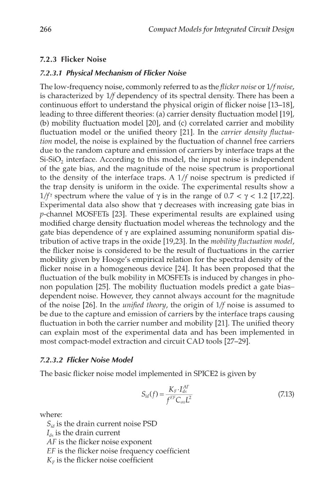
The basic flicker noise model implemented in SPICE2 is given by
S f
K I
f C L
id
F ds
AF
EF
ox
( ) =
⋅
2
(7.13)
where:
S id is the drain current noise PSD
I ds is the drain current
AF is the flicker noise exponent
EF is the flicker noise frequency coefficient
K F is the flicker noise coefficient
Compact Models for Integrated Circuit Design
7.2.3 Flicker Noise
7.2.3.1 Physical Mechanism of Flicker Noise
The low-frequency noise, commonly referred to as the flicker noise or 1/f noise,
is characterized by 1/f dependency of its spectral density. There has been a
continuous effort to understand the physical origin of flicker noise [13–18],
leading to three different theories: (a) carrier density fluctuation model [19],
(b) mobility fluctuation model [20], and (c) correlated carrier and mobility
fluctuation model or the unified theory [21]. In the carrier density fluctuation model, the noise is explained by the fluctuation of channel free carriers
due to the random capture and emission of carriers by interface traps at the
Si-SiO 2 interface. According to this model, the input noise is independent
of the gate bias, and the magnitude of the noise spectrum is proportional
to the density of the interface traps. A 1/f noise spectrum is predicted if
the trap density is uniform in the oxide. The experimental results show a
1/f γ spectrum where the value of γ is in the range of 0.7 < γ < 1.2 [17,22].
Experimental data also show that γ decreases with increasing gate bias in
p-channel MOSFETs [23]. These experimental results are explained using
modified charge density fluctuation model whereas the technology and the
gate bias dependence of γ are explained assuming nonuniform spatial distribution of active traps in the oxide [19,23]. In the mobility fluctuation model,
the flicker noise is considered to be the result of fluctuations in the carrier
mobility given by Hooge’s empirical relation for the spectral density of the
flicker noise in a homogeneous device [24]. It has been proposed that the
fluctuation of the bulk mobility in MOSFETs is induced by changes in phonon population [25]. The mobility fluctuation models predict a gate bias–
dependent noise. However, they cannot always account for the magnitude
of the noise [26]. In the unified theory, the origin of 1/f noise is assumed to
be due to the capture and emission of carriers by the interface traps causing
fluctuation in both the carrier number and mobility [21]. The unified theory
can explain most of the experimental data and has been implemented in
most compact-model extraction and circuit CAD tools [27–29].
7.2.3.2 Flicker Noise Model
The basic flicker noise model implemented in SPICE2 is given by
S f
K I
f C L
id
F ds
AF
EF
ox
( ) =
⋅
2
(7.13)
where:
S id is the drain current noise PSD
I ds is the drain current
AF is the flicker noise exponent
EF is the flicker noise frequency coefficient
K F is the flicker noise coefficient